Thin-walled cone workpiece machining process and clamp device thereof
A technology of processing technology and fixture device, which is applied in the field of thin-walled cone workpiece processing technology and its fixture device, can solve problems such as difficult guarantee and easy deformation, and achieve improved disassembly and assembly efficiency, increased rigidity and strength, and standardized interchangeability strong effect
- Summary
- Abstract
- Description
- Claims
- Application Information
AI Technical Summary
Problems solved by technology
Method used
Image
Examples
Embodiment 1
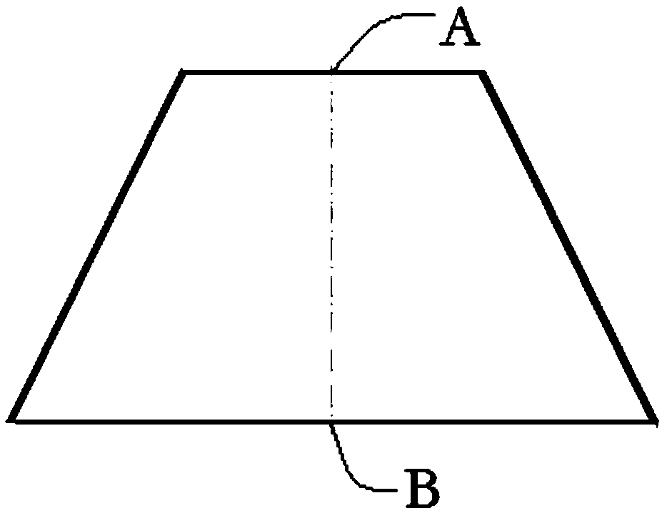
[0052] Such as Figure 1~5 As shown, the present invention provides a clamp device for processing thin-walled cone workpieces. The cone workpiece includes a large end surface B and a small end surface A; it includes a first clamp mechanism 1 for radial fixation and a first clamp mechanism for axial fixation. Fixed second clamp mechanism 2.
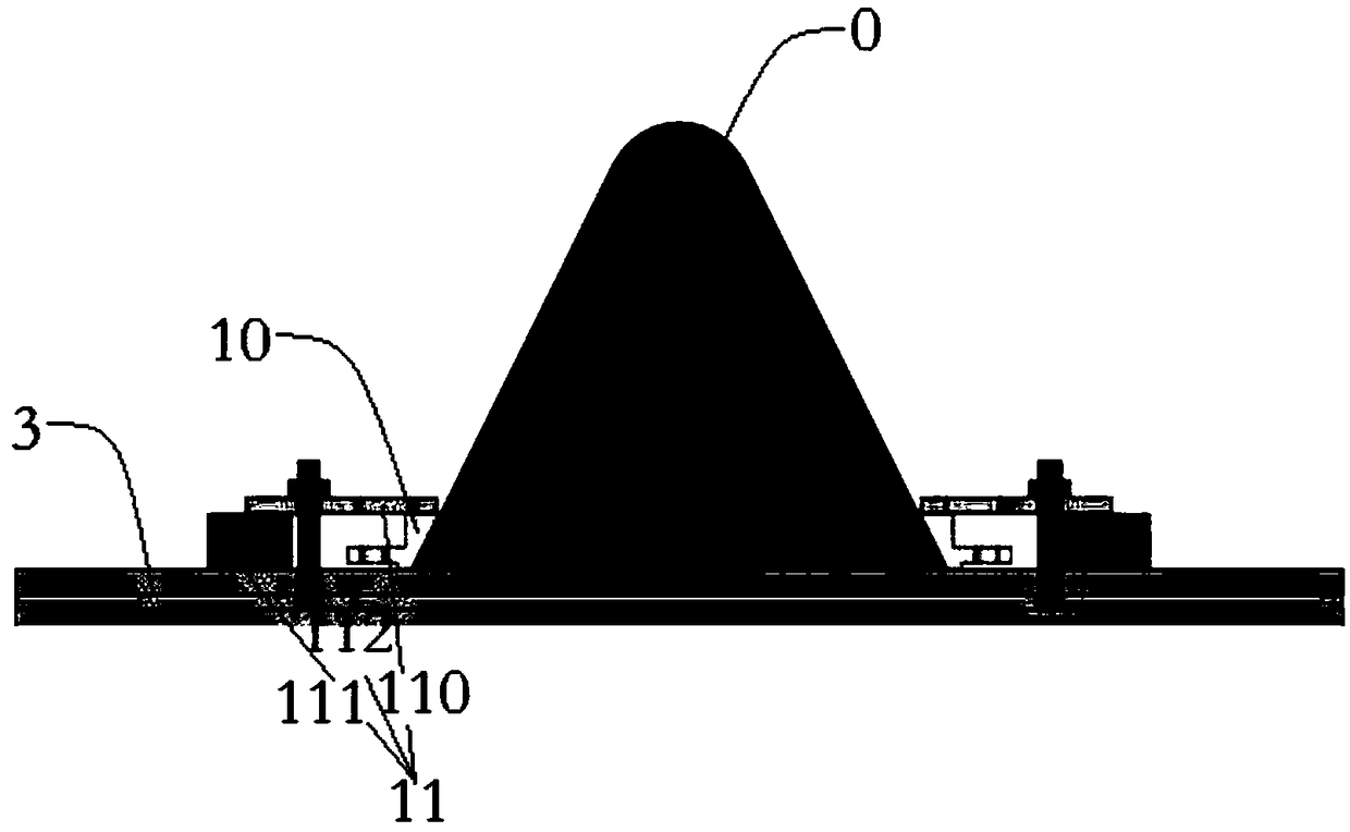
[0053] Such as figure 2 As shown, the first clamp mechanism 1 includes a taper sleeve 10 and a taper sleeve fixing device 11, and the taper sleeve 10 and the taper sleeve fixing device 11 are matched and fixed by bolts 112.
[0054] The cone sleeve fixing device 11 includes a pressure plate 110 and a contour block 111 arranged on the same platform as the cone sleeve. The contour block 111 and the cone sleeve 10 have the same height. The pressure plate 110 is arranged on the contour block 111 and the cone sleeve 10, and the pressure plate 110 Connect with the platform 3 through the bolt 112, and compress the contour block 111 and the taper sle...
Embodiment 2
[0057] The purpose of this embodiment is to provide a second clamp 2 for turning the flange edge of the spinning process.
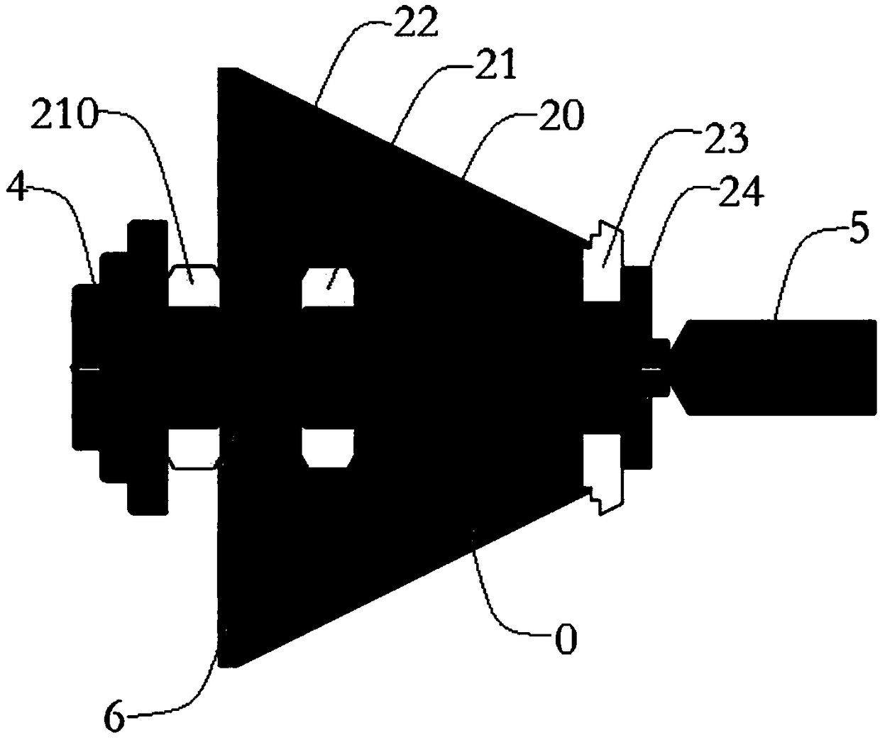
[0058] Such as image 3 As shown, the second clamp mechanism 2 includes a mandrel 20, a lock nut 21, an expansion plate 22, a limit plate 23 and an expansion nut 24. The lock nut 21 and the expansion nut 24 are arranged on the mandrel 20 to expand The clamping plate 22 is locked by the lock nut 21 and abuts against the inner side of the cone workpiece 0, the limit plate 23 is locked by the expansion nut 24 and abuts against the small end surface of the cone workpiece 0, and the mandrel 20 passes through the cone workpiece 0 Inside, one end is clamped by the jaw 4, and the other end is abutted and fixed with the top 5; the jaw 4 and the top 5 are set on a lathe for turning cone workpieces; the top 5 applies pretension to the direction of the shaft 20 axis hole The force plays the role of axially fixing the mandrel 20, ensuring the necessary rigidity and stren...
Embodiment 3
[0068] In this embodiment, a clamp device is provided for processing a thin-walled cone workpiece, and includes a first clamp mechanism 1 for radial fixation and a second clamp mechanism 2 for axial fixation.
[0069] The purpose of this embodiment is to provide a fixture device for the process of turning small end faces; including a first fixture mechanism and a second fixture mechanism;
[0070] Such as Figure 4 As shown, the first clamp mechanism 1 includes a taper sleeve 10 and a taper sleeve fixing device 11, and the taper sleeve and the taper sleeve fixing device are matched and fixed by bolts.
[0071] The taper sleeve fixing device 11 includes a baffle 113, which is locked by a lock nut 210 provided on the mandrel 20, the baffle 113 abuts against the large end surface, the baffle 113 is provided with a taper sleeve, and the taper sleeve 10 The bolt 112 is fixedly connected to the baffle 113, and the taper sleeve 10 abuts against the outer side of the large end surface.
[007...
PUM
 Abstract
Description
Claims
Application Information
 - R&D
- Intellectual Property
- Life Sciences
- Materials
- Tech Scout
- Unparalleled Data Quality
- Higher Quality Content
- 60% Fewer Hallucinations
Browse by: Latest US Patents, China's latest patents, Technical Efficacy Thesaurus, Application Domain, Technology Topic, Popular Technical Reports.
© 2025 PatSnap. All rights reserved.Legal|Privacy policy|Modern Slavery Act Transparency Statement|Sitemap|About US| Contact US: help@patsnap.com


