Lubricating structure of speed reduction transmission device for gas turbine

A technology of deceleration transmission and lubrication structure, applied in transmission parts, gear lubrication/cooling, mechanical equipment, etc., can solve the problems of inability to lubricate and cool the sun gear shaft, low lubricating oil utilization rate, and inability to cool the sun gear shaft, etc. The overall structure is ingenious, the lubrication and cooling effect is good, and the service life is prolonged.

Inactive Publication Date: 2018-05-22
CAS HEFEI MICRO GAS TURBINE RES INST CO LTD
View PDF0 Cites 3 Cited by
  • Summary
  • Abstract
  • Description
  • Claims
  • Application Information

AI Technical Summary

Problems solved by technology

The lower planetary gear in the oil-immersed lubrication method is below the liquid level for a long time, and the lubricating oil is brought to the sun gear shaft and other planetary gears during operation. This lubrication method cannot perform good lubrication and cooling on the sun gear shaft; the forced lubrication method One-side or double-side oil injection above the middle planetary gear realizes the lubrication of the planetary gear and sun gear shaft, but the utilization rate of the injected lubricating oil is low, and it cannot cool the inside of the sun gear shaft well

Method used


Image

  • Lubricating structure of speed reduction transmission device for gas turbine
  • Lubricating structure of speed reduction transmission device for gas turbine
  • Lubricating structure of speed reduction transmission device for gas turbine

Examples


Embodiment Construction

[0025] In order to make the object, technical solution and advantages of the present invention clearer, the present invention will be further described in detail below with reference to the accompanying drawings and examples. It should be noted that implementations not shown or described in the accompanying drawings are forms known to those of ordinary skill in the art. In addition, the directional terms mentioned in the following embodiments, such as "upper", "lower", "front", "backward", "left", "right", "top", "bottom", etc., are only for reference The orientation of the graph. Accordingly, the directional terms are used to illustrate and not to limit the invention.

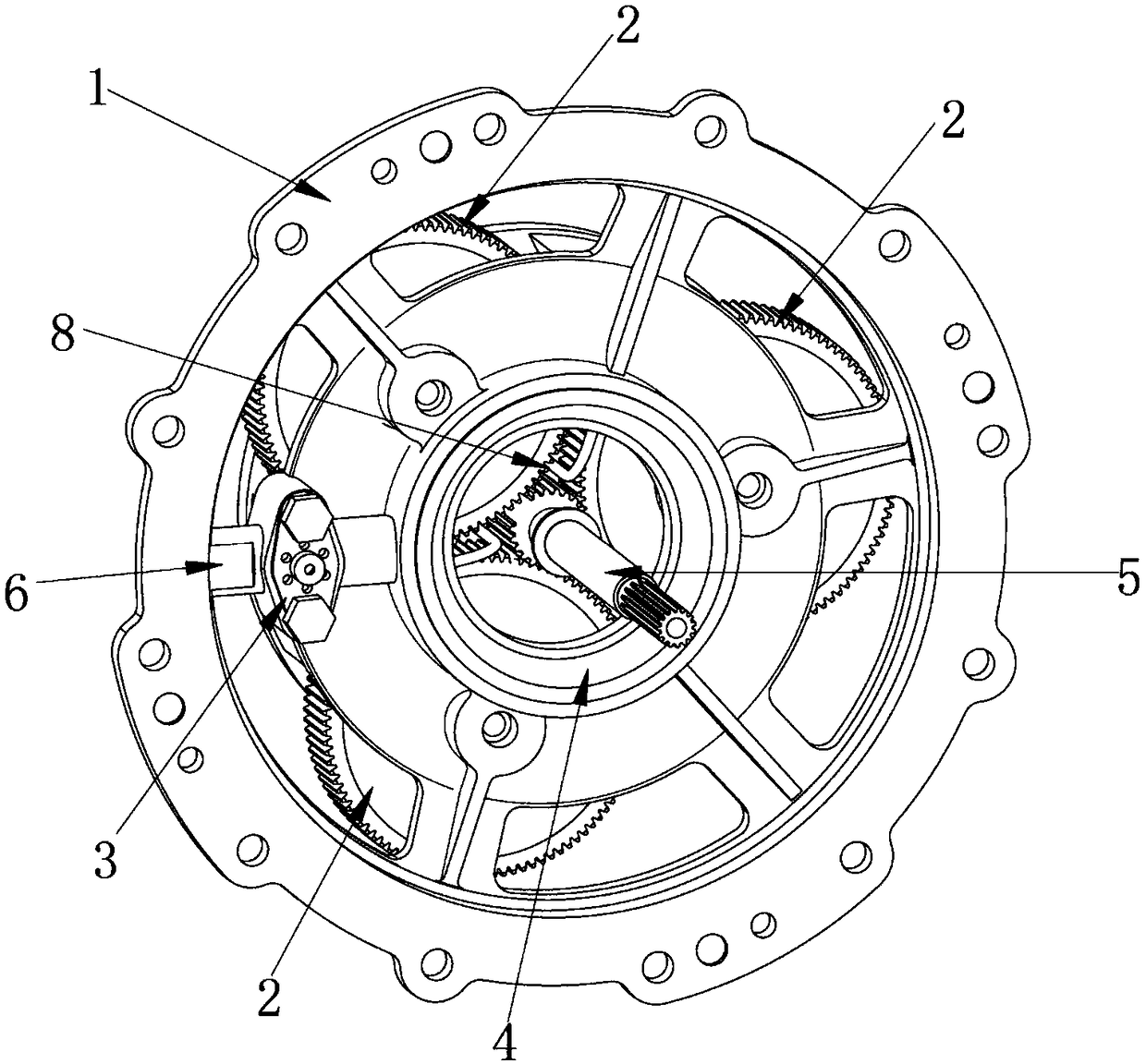
[0026] Such as figure 1 As shown, the lubricating structure of the gas turbine reduction transmission device of the present invention, the reduction transmission device includes a central gear shaft 5, a gear frame 1, and several transmission gears 2 circumferentially arranged on the gear frame 1, and the ge...


PUM


Abstract

The invention discloses a lubricating structure of a speed reduction transmission device for a gas turbine. The speed reduction transmission device comprises a sun gear shaft, a gear holder and a plurality of transmission gears, wherein the transmission gears are uniformly distributed on the gear holder in the circumferential direction; a lubricating oil distributing ring is arranged at the oil outlet end of a lubricating oil channel in the gear holder; an annular oil supply base of the lubricating oil distributing ring is embedded into a center hole of the gear holder and forms a closed oil way ring cavity; a radial oil spraying hole in each radial oil spraying pipeline guides lubricating oil to be sprayed to meshing points of the sun gear shaft and the transmission gears in the radial direction; and a tail end oil spraying hole in an axial nozzle is right opposite to a front end oil inlet of a central lubricating oil passage, guides the lubricating oil to flow to the rear end of thesun gear shaft and further distributes the lubricating oil distribution. The lubricating structure has the advantages that the overall structure is ingenious, the oil pressure is stable, the lubricating and cooling effects on friction pairs such as the sun gear shaft and the transmission gears are good, and guarantees can be provided for weight reduction, stable and reliable operation and prolongation of the service life of the gas turbine.

Description

technical field [0001] The invention relates to the technical field of gas turbines, and relates to a lubricating structure of a reduction transmission device, in particular to a lubrication structure of a reduction transmission device for a gas turbine. Background technique [0002] During the operation of the gas turbine, it is necessary to lubricate and cool the shafts, gears and bearings inside the reduction transmission device. If there is no good lubrication and cooling, the power and service life of the gas turbine will be affected. During normal operation, the gas turbine needs to be supplied with lubricating oil on the working surfaces such as bearings and gears, which can form a continuous oil film, thereby reducing friction damage between structures, and taking away heat from friction and high-temperature parts at the same time, so as to maintain parts. Within the normal operating temperature range, improve the service life of parts. The lubrication methods of th...

Claims


Application Information

Patent Timeline
Patent Type & Authority Applications(China)
IPC IPC(8): F16H57/04
CPCF16H57/0404F16H57/0423F16H57/0435F16H57/0436F16H57/0456F16H57/046
Inventor 徐泽鹏谭春青张睿刚尚伟张志超高文影张前社何昕
Owner CAS HEFEI MICRO GAS TURBINE RES INST CO LTD
Why Eureka
Try Eureka