Gap measuring tool

A technology for measuring tools and gaps, applied in the direction of mechanical gap measurement, etc., to achieve the effect of fast and simple assembly, conforming to operating habits, and convenient operation

Inactive Publication Date: 2018-05-22
HEBEI HUABEI DIESEL ENGINE
View PDF6 Cites 5 Cited by
  • Summary
  • Abstract
  • Description
  • Claims
  • Application Information

AI Technical Summary

Problems solved by technology

[0003] The speed sensor is usually installed on the flywheel housing. The gap between the speed sensor and the speed measuring toothed disc is the axial clearance. The axial clearance to be measured is between the back of the flywheel housing and the speed measuring toothed disc. It cannot be measured directly with a feeler gauge.

Method used


Image

  • Gap measuring tool
  • Gap measuring tool
  • Gap measuring tool

Examples


Embodiment Construction

[0034] Below in conjunction with accompanying drawing and specific embodiment the present invention is described in further detail:

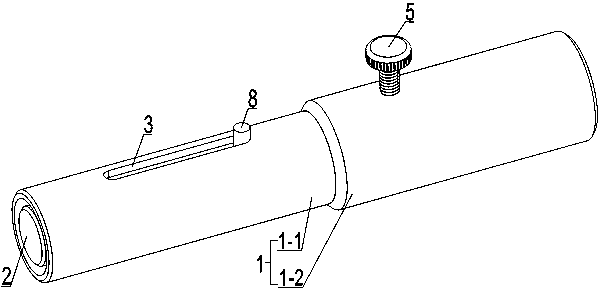
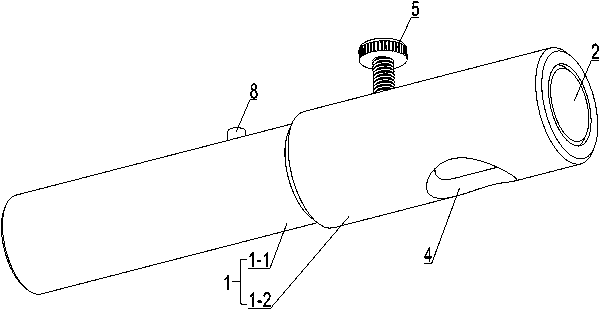
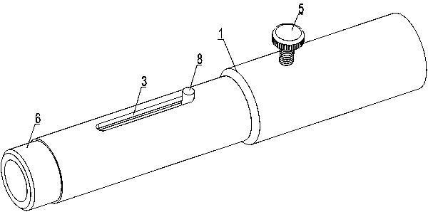
[0035] The invention discloses a gap measuring tool, which can measure the distance at the gap where a feeler gauge cannot easily reach, and is especially suitable for use when a speed sensor is installed on a flywheel housing of an engine. A through hole is provided on the flywheel housing for installing a rotational speed sensor. The following are specific examples:

[0036] Gap measurement tool of the present invention, such as figure 1 , figure 2 As shown, it includes a sleeve 1 and a measuring shaft 2 set in the sleeve 1 and having the same length as the sleeve 1 . The measuring shaft 2 can slide along the axis in the sleeve 1. During use, the measuring shaft 2 slides until one end contacts with the speed measuring chainring, thereby converting the gap to be measured between the back of the flywheel housing of the engine and the speed m...


PUM


Abstract

The invention relates to a gap measuring tool, which belongs to the technical field of measuring tools. The gap measuring tool comprises a sleeve and a measuring shaft, wherein the measuring shaft issleeved in the sleeve and is consistent with the length of the sleeve; the side wall of the sleeve is provided with a limiting groove communicated with the inner cavity of the sleeve and the other endis provided with an observation hole communicated with the inner cavity of the sleeve; the side wall of the sleeve is also provided with a threaded hole and a matched fastening screw; and the measuring shaft is provided with a blind hole for fixing a limiting pin. Through the sleeve and the measuring shaft capable of sliding in the sleeve, a gap at a place which is not easy to measure can be converted through sliding of the measuring shaft, and the measurement operation is facilitated. When the measuring tool is used, multiple times of measurement are not needed, the operation steps can be saved, and errors generated during measurement can also be reduced. The structure is simple, the arrangement is reasonable, the processing and the making are convenient, the operation is easy, the measurement errors are small, the measurement precision is high, the application range is wide, and the integrated use performance is good.

Description

technical field [0001] The invention relates to a gap measuring tool and belongs to the technical field of measuring tools. Background technique [0002] It is usually necessary to install a speed sensor on the engine to measure the speed. It is advisable that the speed sensor should not be in contact with the speed measuring toothed plate when installing, and it is hoped that the gap can be minimized to increase the output signal amplitude, so that the measurement is more accurate. [0003] The speed sensor is usually installed on the flywheel housing. The gap between the speed sensor and the speed measuring toothed disc is the axial clearance. The axial clearance to be measured is between the back of the flywheel housing and the speed measuring toothed disc. It cannot be measured directly with a feeler gauge. . In order to solve this problem and facilitate the operation, the design and invention are carried out on the principle of the original assembly method, the positio...

Claims


Application Information

Patent Timeline
Patent Type & Authority Applications(China)
IPC IPC(8): G01B5/14
CPCG01B5/14
Inventor 何晓燕王保民胡卫中李建新张志军邝明飞郭增元史喜英李慧恩张迎成
Owner HEBEI HUABEI DIESEL ENGINE
Why Eureka
Try Eureka