
Array substrate and manufacturing method thereof, touch display panel, and touch display device

A technology for touch display panels and array substrates, applied in the fields of array substrates and their manufacture, and touch display devices, which can solve problems such as sputtering chamber pollution and increased power consumption of touch display panels

Active Publication Date: 2019-10-22
BOE TECH GRP CO LTD +1
View PDF6 Cites 0 Cited by
  • Summary
  • Abstract
  • Description
  • Claims
  • Application Information

AI Technical Summary

Problems solved by technology

[0004] However, in the above-mentioned array substrate, the pixel electrode is located on the side of the common electrode facing away from the thin film transistor. When the touch display panel provided with the above-mentioned array substrate is in operation, in the display stage, there It is easy to form a large capacitance. Therefore, in order to achieve a good display of the touch display panel, it is usually necessary to increase the size of the common voltage signal provided for the common electrode, resulting in an increase in power consumption of the touch display panel; at the same time, the above array In the substrate, the touch electrodes are formed on the insulating planarization layer. At present, the material of the touch electrode is usually metal, and the touch electrode is usually formed by a sputtering process. The material of the insulating planarization layer is usually an organic material, so sputtering is used. When the touch electrode is formed by the sputtering process, it is easy to cause the insulating planarization layer to decompose in the sputtering chamber with a higher temperature, resulting in pollution of the sputtering chamber

Method used


Image

  • Array substrate and manufacturing method thereof, touch display panel, and touch display device
  • Array substrate and manufacturing method thereof, touch display panel, and touch display device
  • Array substrate and manufacturing method thereof, touch display panel, and touch display device

Examples


Embodiment Construction

[0064] In order to further illustrate the array substrate and the manufacturing method thereof, the touch display panel, and the touch display device provided by the embodiments of the present invention, a detailed description will be given below in conjunction with the accompanying drawings.

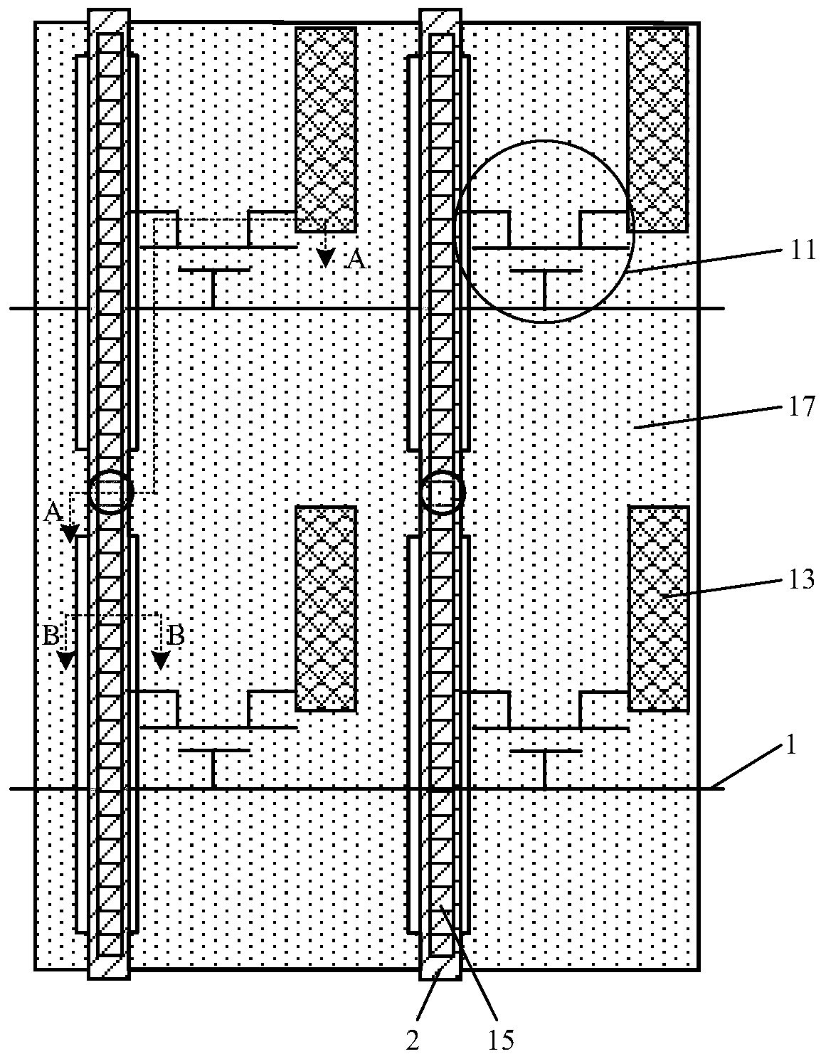
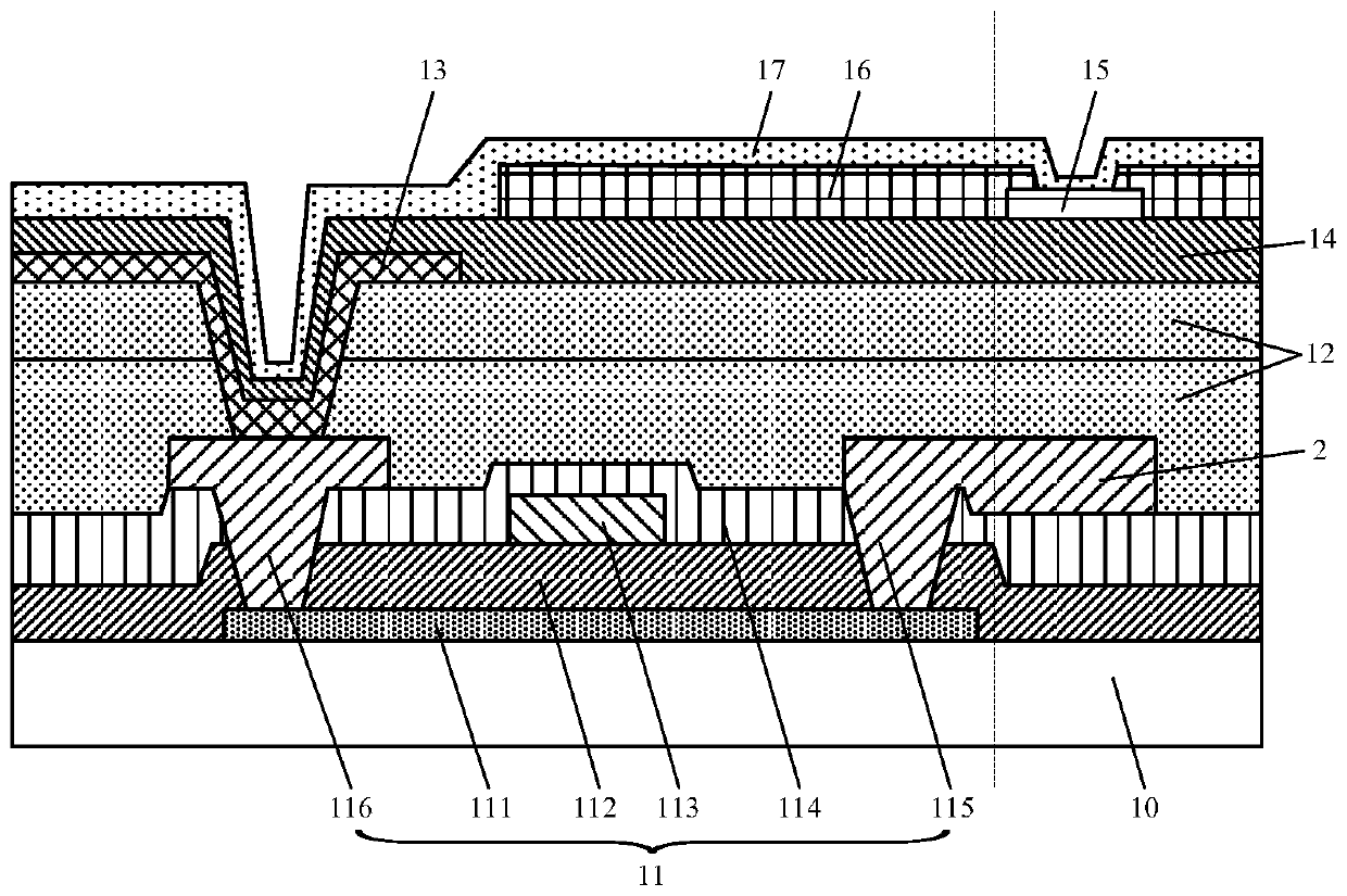
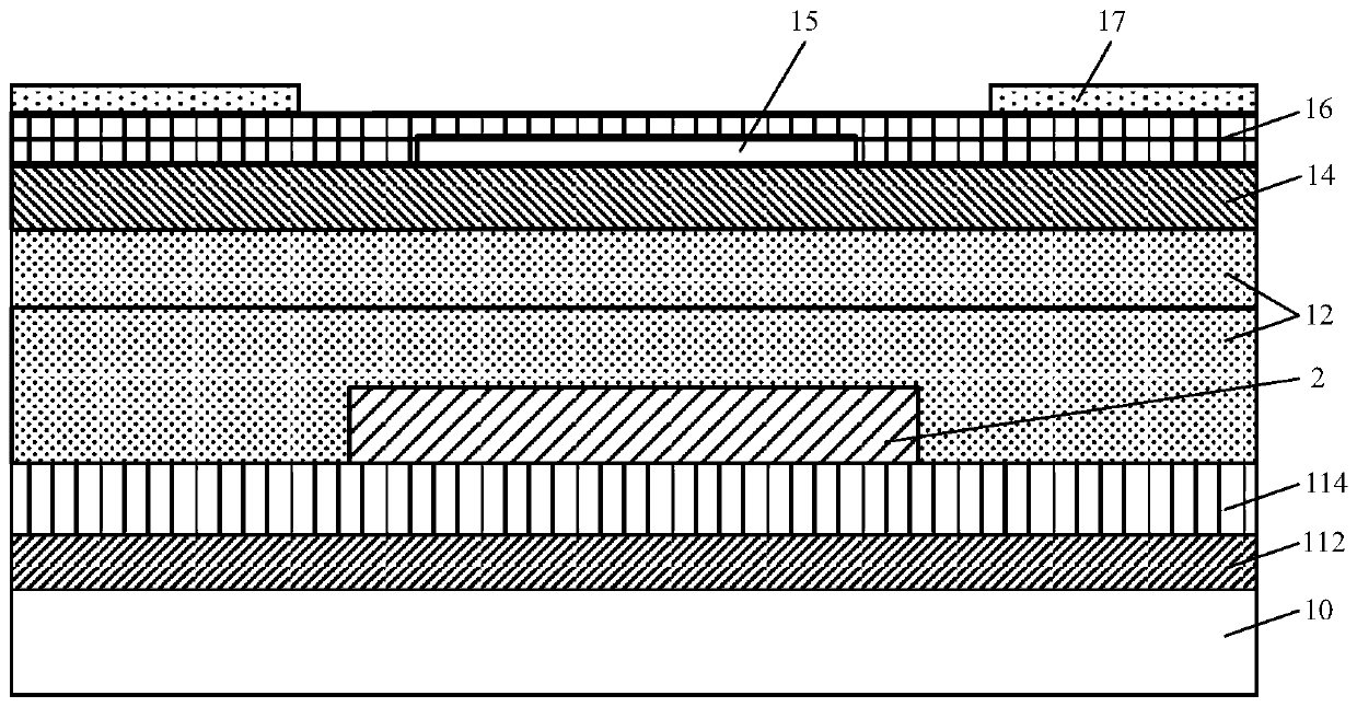
[0065] see figure 1 and figure 2 , the array substrate provided by the embodiment of the present invention includes: a thin film transistor 11 formed on a base substrate 10; an insulating planarization layer 12, the insulating planarization layer 12 is located on the thin film transistor 11, and the insulating planarization layer 12 has an exposed thin film The via hole of the drain 116 of the transistor 11; the pixel electrode 13, the pixel electrode 13 is located on the side of the insulating planarization layer 12 facing away from the thin film transistor 11, the pixel electrode 13 passes through the via hole in the insulating planarization layer 12 and the thin film transistor 11 ...


PUM

PropertyMeasurementUnit
thicknessaaaaaaaaaa
thicknessaaaaaaaaaa
thicknessaaaaaaaaaa

Abstract

The invention discloses an array substrate and its manufacturing method, a touch display panel, and a touch display device, which relate to the technical field of touch display and are used to reduce the power consumption of the touch display panel during operation, and at the same time avoid Metallic touch electrodes cause contamination of the sputtering chamber. The array substrate includes: a thin film transistor formed on the base substrate; an insulating planarization layer, the insulating planarization layer is located on the thin film transistor, and the insulating planarization layer has a via hole exposing the drain of the thin film transistor; the pixel electrode, The pixel electrode is located on the side of the insulating planarization layer facing away from the thin film transistor, and the pixel electrode is connected to the drain of the thin film transistor through the via hole in the insulating planarizing layer; the touch electrode is located on the side of the insulating planarization layer facing away from the pixel electrode. one side; the common electrode, the common electrode is located on the side of the touch electrode facing away from the pixel electrode, and the common electrode is connected to the corresponding touch electrode.

Description

technical field [0001] The present invention relates to the technical field of touch display, in particular to an array substrate and a manufacturing method thereof, a touch display panel, and a touch display device. Background technique [0002] A touch display device is a device that can realize both display and touch control. At present, a touch display device usually includes a touch display panel, and a touch display panel usually includes a display panel and a touch panel. According to the touch panel and The relative positional relationship of the display panel can be divided into a built-in touch display panel and an out-cell touch display panel (Out-cell). Touch display panel (In-cell, also known as in-cell touch display panel) and built-in surface touch display panel (On-cell), because the built-in in-surface touch display panel (In-cell) is convenient Manufacture of light and thin products has been extensively researched and applied. [0003] An existing built-i...

Claims


Application Information

Patent Timeline
Patent Type & Authority Patents(China)
IPC IPC(8): G09F9/30G06F3/041G02F1/1333G02F1/1343
CPCG02F1/133345G02F1/13338G02F1/1343G06F3/0412G09F9/30G02F1/133357G06F2203/04103G06F3/04164G06F3/0443G02F2201/40
Inventor 马明超樊君李付强
Owner BOE TECH GRP CO LTD
Learn More