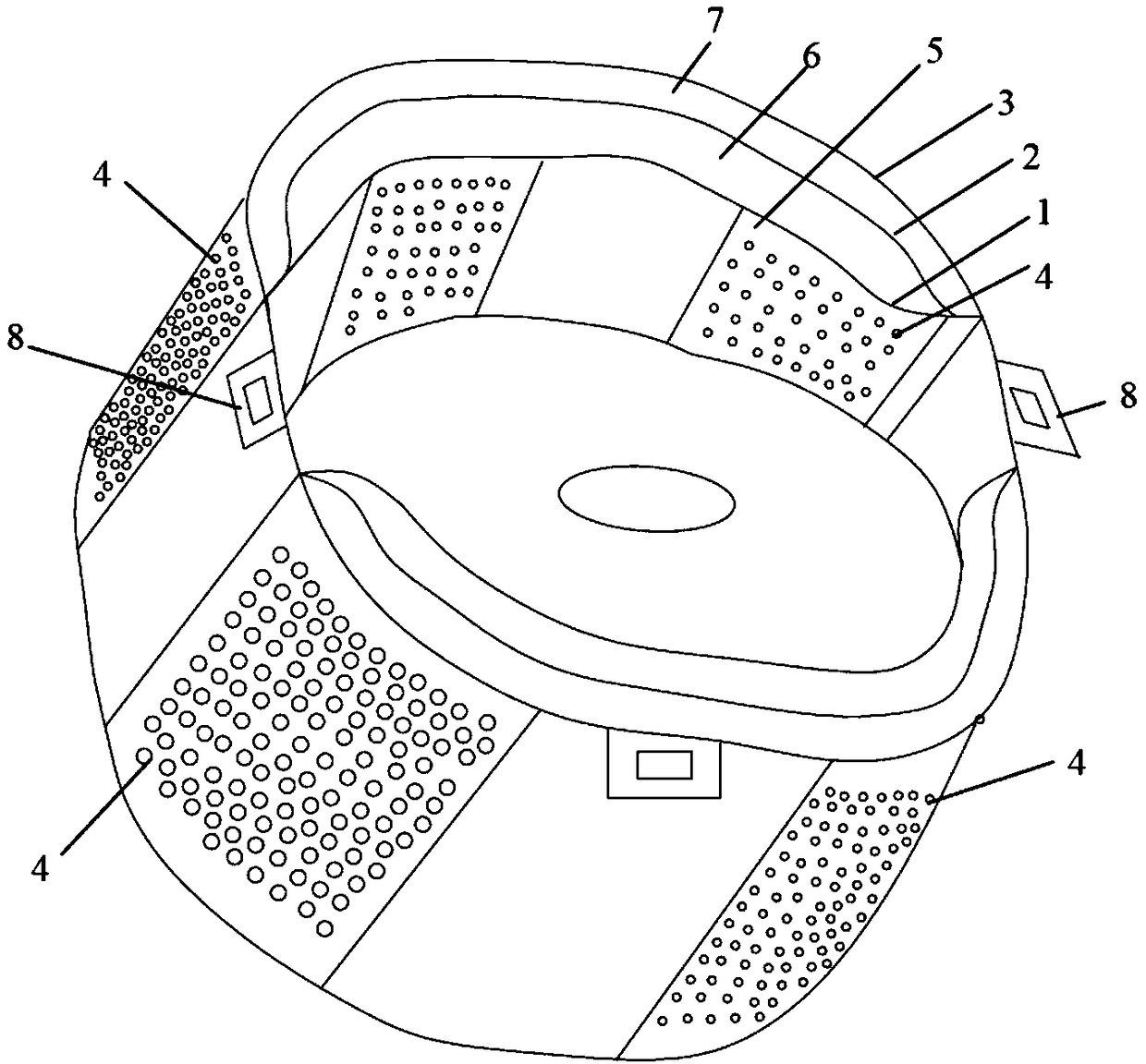
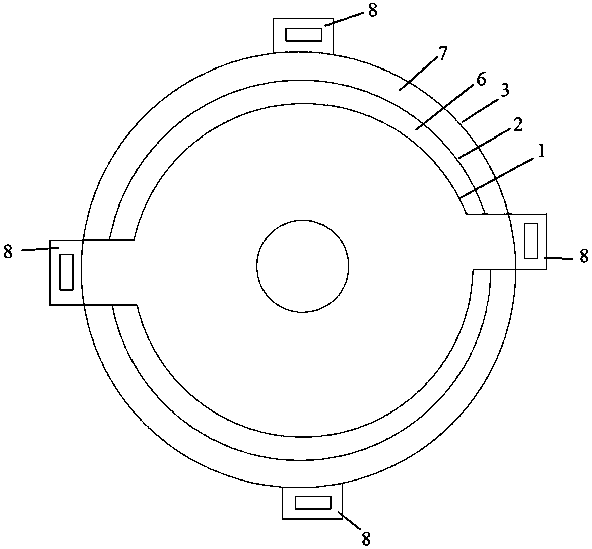
Low-noise air discharging device for dust collector
A technology for exhaust devices and vacuum cleaners, applied in the direction of vacuum cleaners, exhaust diffusers, cleaning equipment, etc., can solve the problems of reducing the flow speed of air discharge, high-speed disturbance, and no noise absorption without setting, and achieve simple structure and exhaust effect Good, low manufacturing cost effect
- Summary
- Abstract
- Description
- Claims
- Application Information
AI Technical Summary
Problems solved by technology
Method used
Image

Examples
Embodiment 1
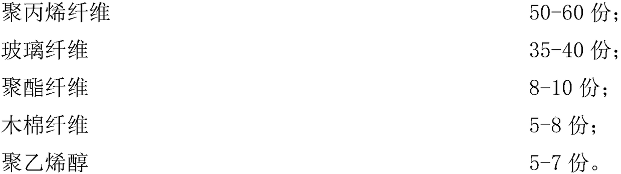
[0042] (1) first utilize the roller press machine to supply the polypropylene fiber material of 60 weight parts to the first roller;
[0043] (2) 35 parts by weight of glass fibers are then supplied to the second roll;
[0044] (3) 8 polyester fibers, the kapok fiber of 8 weight parts and the polyvinyl alcohol of 6 weight parts are mixed, and the mixture is supplied between the first roll and the second roll;
[0045] (4) Due to the back tension between the first roll and the second roll, the fiber material on the two rolls is mixed with polyester fiber, kapok fiber and polyvinyl alcohol to combine to make the non-woven sound-absorbing material required by the present invention , the thickness is 0.5mm.
Embodiment 2
[0047] (1) first utilize the roller press machine to supply the polypropylene fiber material of 60 weight parts to the first roller;
[0048] (2) 35 parts by weight of glass fibers are then supplied to the second roll;
[0049] (3) 8 polyester fibers, 8 weight parts of kapok fibers and 5 weight parts of polyvinyl alcohol are mixed uniformly, and the mixture is supplied between the first roll and the second roll;
[0050] (4) Due to the back tension between the first roll and the second roll, the fiber material on the two rolls is mixed with polyester fiber, kapok fiber and polyvinyl alcohol to combine to make the non-woven sound-absorbing material required by the present invention , the thickness is 0.4mm.
Embodiment 3
[0052] (1) first utilize the roller press machine to supply the polypropylene fiber material of 60 weight parts to the first roller;
[0053] (2) 35 parts by weight of glass fibers are then supplied to the second roll;
[0054] (3) 8 polyester fibers, the kapok fiber of 8 weight parts and the polyvinyl alcohol of 7 weight parts are mixed, and the mixture is supplied between the first roll and the second roll;
[0055] (4) Due to the back tension between the first roll and the second roll, the fiber material on the two rolls is mixed with polyester fiber, kapok fiber and polyvinyl alcohol to combine to make the non-woven sound-absorbing material required by the present invention , the thickness is 0.3mm.
PUM
 Abstract
Description
Claims
Application Information
 - R&D
- Intellectual Property
- Life Sciences
- Materials
- Tech Scout
- Unparalleled Data Quality
- Higher Quality Content
- 60% Fewer Hallucinations
Browse by: Latest US Patents, China's latest patents, Technical Efficacy Thesaurus, Application Domain, Technology Topic, Popular Technical Reports.
© 2025 PatSnap. All rights reserved.Legal|Privacy policy|Modern Slavery Act Transparency Statement|Sitemap|About US| Contact US: help@patsnap.com