Metal cutter

A cutting knife and metal technology, applied in metal processing equipment, metal processing machinery parts, shearing devices, etc., can solve the problem of high replacement cost

Pending Publication Date: 2018-05-25
成都格力钛新能源有限公司 +1
View PDF21 Cites 0 Cited by
  • Summary
  • Abstract
  • Description
  • Claims
  • Application Information

AI Technical Summary

Problems solved by technology

[0004] For this reason, the technical problem to be solved by the present invention is that the damage of a part of the blade of the cutting tool in the prior art needs to replace the entire tool, which is expensive to replace, and then provides a metal cutter that is not easy to break and has low replacement cost

Method used


Image

  • Metal cutter
  • Metal cutter
  • Metal cutter

Examples


Embodiment 1

[0027] The metal cutter of this embodiment is arranged on the rotating shaft 2, and the metal cutting knife includes two blades 1, and a guard 3 is arranged between the blade 1 and the rotating shaft 2, and the guard 3 is used for the blade 1 to encounter more than When the hard material 4 of the hardness is set, the transmission between the blade 1 and the rotating shaft 2 becomes invalid.

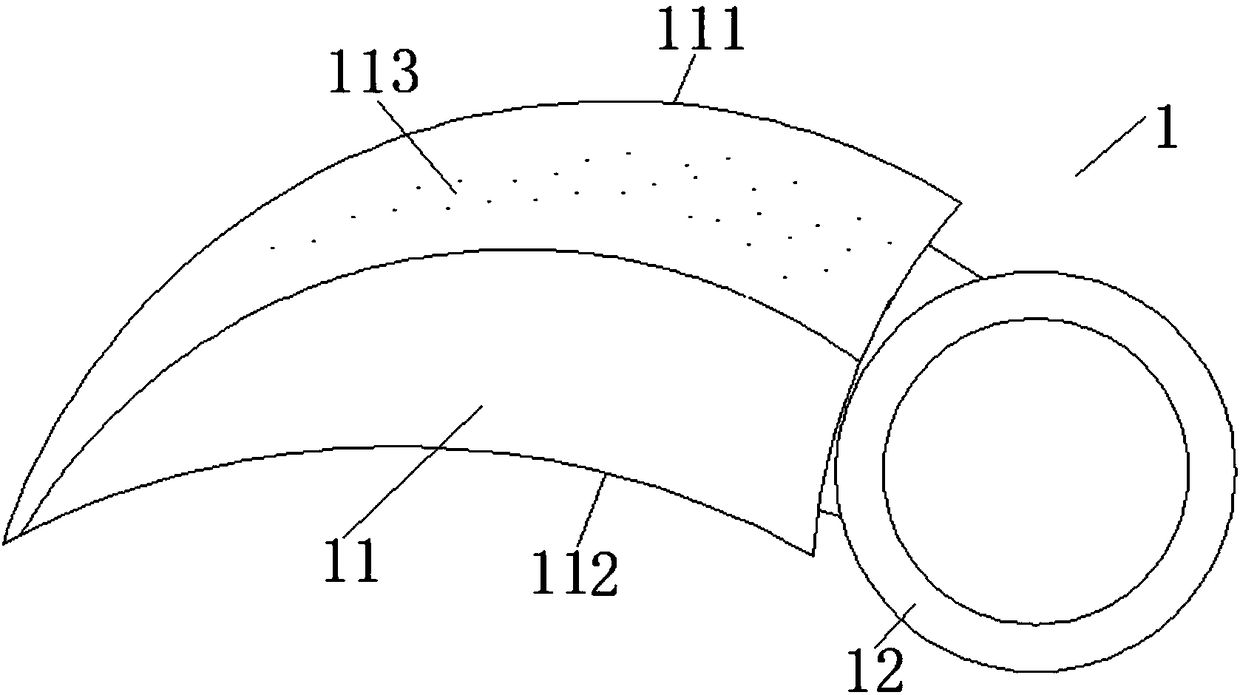
[0028] figure 1 Shown is the blade 1 in this embodiment. The blade 1 includes a blade body 11 and a blade ring 12 integrally formed with the blade body 11 . The blade ring 12 is suitable for being sleeved on the rotating shaft 2 .

[0029] The protection device 3 includes a fixing part 31 for fixing the knife ring 12. The fixing part 31 radially passes through the knife ring 12 and presses against the rotating shaft 2, and presses against the rotating shaft. When the blade 1 meets a hard material 4 with a hardness greater than the set There is slippage between the fixing member 31 and th...

Embodiment 2

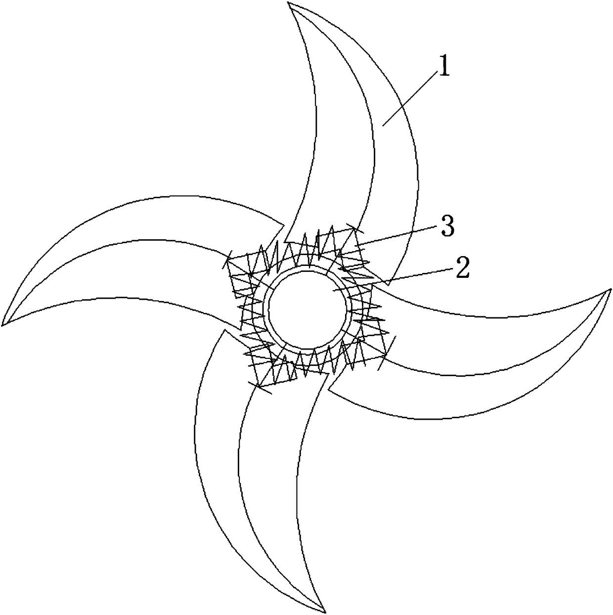
[0031] image 3 Shown is the metal cutter of this embodiment, which is arranged on the rotating shaft 2. The metal cutting knife includes 4 blades 1. In this embodiment, the blades 1 are uniformly arranged around the rotating shaft 2. Between the blades 1 and the rotating shaft 2, there is a The protection device 3 is used to make the transmission between the blade 1 and the rotating shaft 2 ineffective when the blade 1 encounters a hard material 4 with a hardness greater than a set hardness during cutting.

[0032] figure 1 Shown is the blade 1 in this embodiment. The blade 1 includes a blade body 11 and a blade ring 12 integrally formed with the blade body 11 . The blade ring 12 is suitable for being sleeved on the rotating shaft 2 .

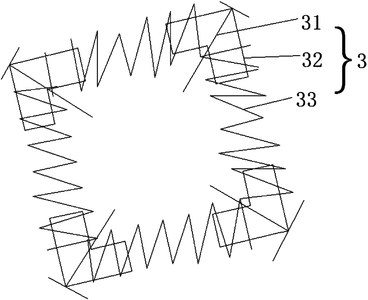
[0033] The protective device 3 includes a fixing part 31 for fixing the knife ring 12, a transmission part 32 fixedly arranged on the blade 1, and an elastic conductive part 33. The fixing part 31 radially passes through the knife ring 12 and...

Embodiment 3

[0036] Figure 4 Shown is the metal cutter in this embodiment, the metal cutter includes several blades 1, the number of blades in this embodiment is 4, but not limited to this number, it can also be 3 or 5, the blade 1 and the rotating shaft 2 is provided with a protective device 3, the protective device 3 transmits the force of the rotating shaft 2 to the blade 1, and makes the transmission between the blade 1 and the rotating shaft 2 invalid when the blade 1 cuts hard material 4 with a hardness greater than the set hardness. The blade 1 includes a cutter body 11 and a cutter ring 12 integrally formed with the cutter body 11 , and the cutter ring 12 is suitable for being sleeved on the rotating shaft 2 . The protection device 3 includes a fixing part 31 for fixing the knife ring 12. The fixing part 31 radially passes through the knife ring 12 and presses the rotating shaft 2 against the inner wall of the knife ring. When the blade 1 meets the hard material 4, the fixing part...


PUM


Abstract

The invention relates to a tool, in particular to a metal cutter arranged on a rotating shaft. The metal cutter comprises a plurality of blades. A protecting device is arranged between the blades andthe rotating shaft and used for enabling transmission between the blades and the rotating shaft to lose efficacy when the blades meet hard materials with hardness higher than set hardness in the cutting process. According to the technical problem to be solved, when a part of blades of a cutting tool in the prior art is damaged, the whole tool needs to be replaced, the replacing cost is high, and then the metal cutter which cannot be damaged easily and is low in replacing cost is provided.

Description

technical field [0001] The invention relates to a knife, in particular to a metal cutting knife. Background technique [0002] During the production or disassembly of metal products (such as pole pieces, flexible connections, battery cases, auto parts), metal products include materials with more than one hardness, and often have a mixture of materials with multiple hardness. When cutting with a tool When this material is mixed, tool breakage often occurs. [0003] Chinese patent document CN202192332U discloses a metal cutting sheet, which includes a cutting base, the center of the cutting base is provided with a fixing hole, and a number of cutting blades made of tungsten steel are evenly distributed on the edge of the cutting base, and the cutting blades and The cutting base is fixedly set or integrally formed. That is to say, the cutting knife body is rigidly connected with the cutting substrate. Therefore, during the cutting process, the knife is prone to breakage when ...

Claims


Application Information

Patent Timeline
Patent Type & Authority Applications(China)
IPC IPC(8): B23D35/00B23Q11/00
CPCB23D35/001B23D35/002B23Q11/00
Inventor 李娟李前干徐冬阳
Owner 成都格力钛新能源有限公司
Why Eureka
Try Eureka