Tourniquet automatic access device

An automatic access and tourniquet technology, applied in the field of medical devices, can solve the problem of tourniquet tourniquet ends remaining in the storage box, etc., and achieve the effect of avoiding bacterial infection

Active Publication Date: 2020-07-24
THE FIRST AFFILIATED HOSPITAL OF ARMY MEDICAL UNIV
View PDF6 Cites 0 Cited by
  • Summary
  • Abstract
  • Description
  • Claims
  • Application Information

AI Technical Summary

Problems solved by technology

[0003] The present invention intends to provide an automatic access device for tourniquets to solve the technical problem that the end of the tourniquet remains in the storage box due to the abnormal breakage of the point-break tourniquet

Method used


Image

  • Tourniquet automatic access device
  • Tourniquet automatic access device
  • Tourniquet automatic access device

Examples


Embodiment 1

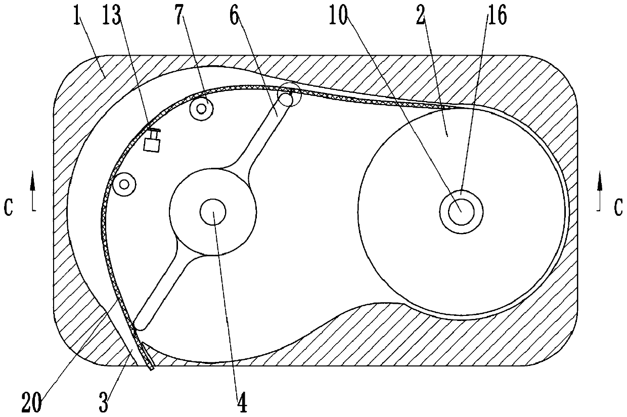
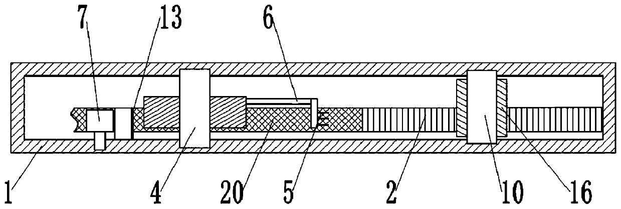
[0033] Basic as attached figure 1 Shown: the tourniquet automatic access device, including a case 1 and a tourniquet roll 2 rotated inside the case 1, a shaft core 10 is clamped inside the case case 1, and a sponge layer is glued on the outer peripheral surface of the shaft core 10 16. The tourniquet roll 2 is sleeved on the outer peripheral surface of the sponge layer 16 with friction. The lower left side of the casing 1 is also opened with a discharge port 3 for taking the tourniquet 20 .

[0034] Such as figure 1 , figure 2 As shown, the left side of the tourniquet roll 2 is provided with a guide mechanism, and the guide mechanism includes a rotating shaft 4 and a guide wheel 7, and the guide wheel 7 is vertically passed through a flange bearing ( figure 2 Angle of view) is rotated and installed in the box shell 1, figure 1 Two guide wheels 7 have been drawn in the middle, and two guide wheels 7 are arranged at the upper left side of rotating shaft 4 at intervals. Tw...

Embodiment 2

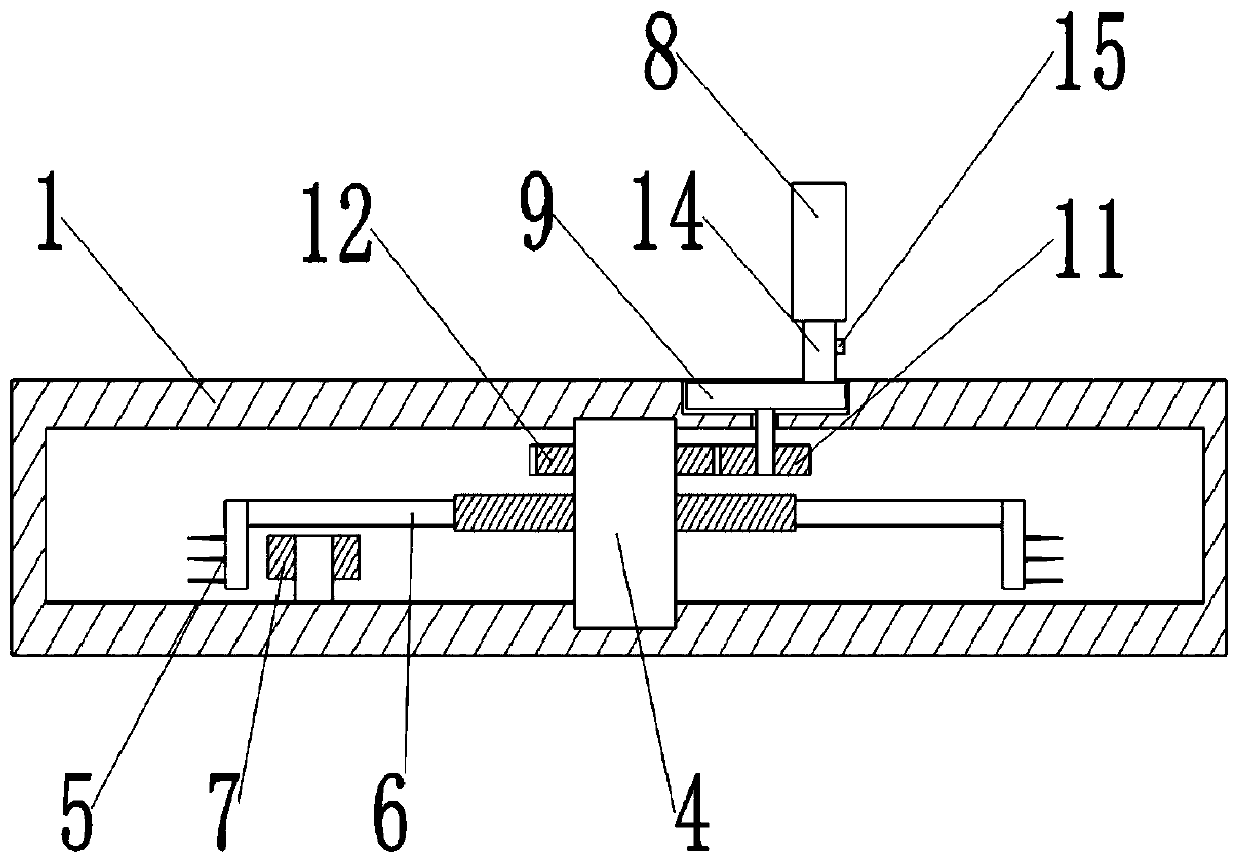
[0039] The difference between this embodiment and Embodiment 1 is that the key switch 15 is driven by the L-shaped connecting rod 6, such as Figure 5 As shown, the key switch 15 is located at the lower left side of the case 1 near the discharge port 3 . Such as Figure 6 As shown, the horizontal height of the L-shaped connecting rod 6 is higher than the upper surface of the key switch 15, so the L-shaped connecting rod 6 can press the trigger part 17 downward when rotating; A trigger part 17 is hingedly connected to the platform 19, and a return spring 18 is fixedly welded between the middle part of the lower end surface of the trigger part 17 and the case shell 1, and the key switch 15 is located below the right end of the trigger part 17.

[0040] When using this solution, the basic principle is the same as that of Embodiment 1; when the L-shaped connecting rod 6 rotates to the position of the discharge port 3, it will squeeze the trigger part 17 downward, and the downward...


PUM


Abstract

The invention relates to the technical field of medical instruments, in particular to an automatic tourniquet storing and taking device. The automatic tourniquet storing and taking device comprises abox shell and a tourniquet roll rotatably arranged in the box shell, wherein the box shell is provided with a discharge port, one side of the tourniquet roll is provided with a guide mechanism, the guide mechanism comprises a rotating shaft, two fixed claws are fixedly arranged on the rotating shaft, and the two fixed claws are symmetrically arranged with respect to the rotating shaft; the invention further comprises a driving mechanism for driving the rotating shaft to rotate, and the driving mechanism is arranged outside the box shell; and one side of the rotating shaft is provided with a cutting mechanism, the cutting mechanism is positioned at the lower side of an L-shaped connecting rod, the cutting mechanism comprises blades and a motor for driving the blade, and a key switch is alsoarranged on the circuit of the motor. By adopting the scheme, a length suitable for use can be cut off the tourniquet roll when the device is in use, and the situation that the tourniquet end part remains in the box body due to abnormal fracture of the point-broken type tourniquet roll is avoided.

Description

technical field [0001] The invention relates to the technical field of medical instruments, in particular to an automatic access device for a tourniquet. Background technique [0002] Tourniquet is a medical device used in blood transfusion, infusion, blood draw, hemostasis and other situations in the medical process. It achieves the purpose of hemostasis by blocking blood flow by compressing blood vessels. The traditional form of tourniquet is a reused rubber tube or rubber strip. With the overall improvement of medical and health requirements and technology, the above-mentioned tourniquet has gradually withdrawn from the stage of history due to the risk of cross-infection, and is replaced by natural rubber. The disposable tourniquet with wide and flat shape, which is individually packaged in strips, improves the hygiene level and effectively prevents the spread of germs. In order to improve the convenience of operation, there are also tourniquets packaged in rolls. This k...

Claims


Application Information

Patent Timeline
Patent Type & Authority Patents(China)
IPC IPC(8): B65H35/08B65H23/26B65H20/20A61B17/132
CPCA61B17/132B65H20/20B65H23/26B65H35/08B65H2301/5153B65H2701/11332
Inventor 杨成雪钟美玲孙丽
Owner THE FIRST AFFILIATED HOSPITAL OF ARMY MEDICAL UNIV
Why Eureka
Try Eureka