Optical measurement method and device with control points

An optical measurement and control point technology, which is applied in the direction of using optical devices, measuring devices, instruments, etc., can solve the problems of difficult layout, low efficiency, and heavy workload of optical measurement mark layout, and achieve high precision, high efficiency, and overcome work A large amount of effect

Inactive Publication Date: 2018-05-25
ZHEJIANG WEISS WIRELESS NETWORK TECH CO LTD
View PDF14 Cites 4 Cited by
  • Summary
  • Abstract
  • Description
  • Claims
  • Application Information

AI Technical Summary

Problems solved by technology

[0013] The present invention provides an optical measurement method and device using control points, which are used to overcome the existing photogrammetry technology, which has a large workload and low efficiency in the layout of optical measurement marks, and it is difficult to deploy on the track and difficult to maintain the track environment for a long time. use at least one of these disadvantages under

Method used


Image

  • Optical measurement method and device with control points
  • Optical measurement method and device with control points

Examples


Embodiment 1

[0034] Example 1: An example of an optical measurement method using control points

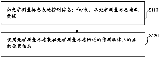
[0035] See figure 1 As shown, an embodiment of an optical measurement method using control points provided by the present invention includes:

[0036] Step S110, sending control information to the optical measurement sign; and / or, receiving data from the optical measurement sign;

[0037] In step S120, the optical measurement mark is used to obtain position information of points on the object to be measured near the optical measurement mark.

[0038] The optical measurement mark serves as a measurement control point.

[0039] Generally, four or more measurement control points are arranged in a scene covered by an optical imaging picture. Typically, four to sixteen measurement control points are arranged. If there are more measurement control points, the measurement error is small.

[0040] The optical measurement indicator, receiving the control information through a wired channel or a wireless channel,...

Embodiment 2

[0183] The second embodiment, an example of an optical measurement device using control points

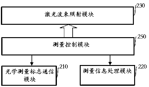
[0184] See figure 2 As shown, an embodiment of an optical measurement device using control points provided by the present invention includes:

[0185] Optical measurement sign communication module 210 and measurement information processing module 220; among them,

[0186] The optical measurement sign communication module 210 is used for sending control information to the optical measurement sign; and / or, receiving data from the optical measurement sign, including a wireless or wired transmission sub-module;

[0187] The measurement information processing module 220 is configured to use the optical measurement mark to obtain position information of points on the object to be measured near the optical measurement mark, and includes a data processing sub-module.

[0188] The device given in this embodiment further includes a laser beam irradiation module 230 and a measurement control module 2...


PUM


Abstract

The invention discloses an optical measurement method and device with control points. The optical measurement method includes the steps that control information is sent to optical measurement marks; and / or data is received from the optical measurement marks; position information of points on to-be-measured objects nearby the optical measurement marks is obtained with the optical measurement marks.The optical measurement method and device with the control points can work in the outdoor environment, and the measurement precision and efficiency are high.

Description

Technical field [0001] The invention relates to the field of automatic measurement, in particular to an optical measurement method and device using control points. Background technique [0002] There are a wide range of application requirements for displacement detection and deformation detection of buildings or industrial facilities. Among them, the displacement or deformation detection of bridges, dams and rails is an important technical means for safe operation and production. [0003] At present, the methods for detecting displacement and deformation of dams and bridges include line-of-sight detection, GPS (Global Navigation System), and the combination of these methods and surface displacement sensors; detection of displacement and deformation of rails (rail transit tracks) Including absolute displacement or deformation measurement based on CPIII (Control Point III), or displacement or deformation measurement based on the characteristics of the total station and measuring vehi...

Claims


Application Information

Patent Timeline
IPC IPC(8): G01B11/02G01B11/16
CPCG01B11/02G01B11/16
Inventor 胡淼龙
Owner ZHEJIANG WEISS WIRELESS NETWORK TECH CO LTD
Why Eureka
Try Eureka