

Orbital photography measurement method and device
A photogrammetry and track technology, which is applied to measuring devices, measuring instruments, and optical devices, etc., can solve the problems of large installation workload, low efficiency, and difficult installation, and achieve high precision, high efficiency, and overcome the problems of heavy workload. Effect
- Summary
- Abstract
- Description
- Claims
- Application Information
AI Technical Summary
Problems solved by technology
Method used
Image

Examples
Embodiment 1
[0034] Embodiment 1, an example of an orbital photogrammetry method
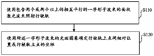
[0035] see figure 1 As shown, a kind of track photogrammetry method embodiment provided by the present invention comprises:
[0036] Step S110, using a planar laser beam comprising two or more inline sub-beams parallel to each other to irradiate the running rail;
[0037] Step S120, using the spot image of the in-line sub-beam to determine the relative position between points on the traveling track or the coordinates of the points on the traveling track.
[0038] In this embodiment, the optical measurement marks are used as measurement control points.
[0039] Usually, four or more measurement control points are arranged in a scene covered by an optical imaging picture, typically, four to sixteen measurement control points are arranged, and the measurement error is smaller if there are more measurement control points.
[0040] The optical measurement flag receives the control information through a wired cha...
Embodiment 2
[0136] Embodiment 2, an example of a photogrammetry device
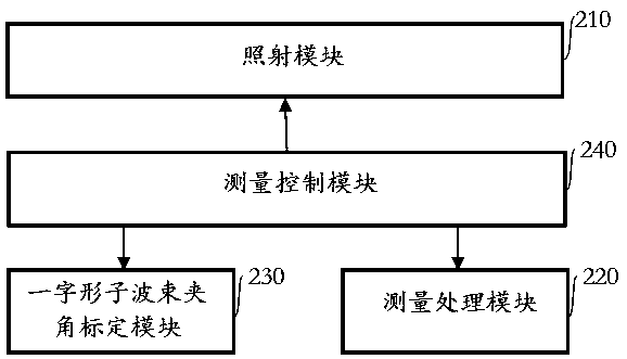
[0137] see figure 2 As shown, an embodiment of a photogrammetry device provided by the present invention includes:
[0138] Irradiation module 210, measurement module 220; Wherein,
[0139] The irradiation module 210 is used to irradiate the driving rail with a planar laser beam containing two or more parallel inline sub-beams, including a laser light source sub-module, a laser beam shaping sub-module, a laser reflection surface sub-module, and an irradiation control module. At least one of the submodule, the irradiation position information acquisition submodule, and the laser reflection surface rotation servo submodule;
[0140] The measurement module 220 is used to determine the relative position between points on the driving rail or the coordinates of points on the driving rail by using the spot image of the inline sub-beam, including at least one of the spot image processing sub-module and the position inform...
PUM
 Abstract
Description
Claims
Application Information