Cultivating liquid storage structure of biosensor

A biosensor and liquid storage technology, applied in the field of cultivation liquid storage structure, can solve the problems of complicated operation and high personnel requirements, and achieve the effects of convenient replacement, complete replacement and rapid liquid discharge.

Pending Publication Date: 2018-05-25
重庆晓微城企业孵化器有限公司
View PDF0 Cites 0 Cited by
  • Summary
  • Abstract
  • Description
  • Claims
  • Application Information

AI Technical Summary

Problems solved by technology

[0004] Aiming at the problems that the existing biosensors proposed above require manual liquid addition, draining and cleaning, cumbersome operation and high requirements for personnel, the present invention provides a storage structure for the cultivation liquid in the biosensor. Features of convenient liquid replacement

Method used


Image

  • Cultivating liquid storage structure of biosensor

Examples


Embodiment 1

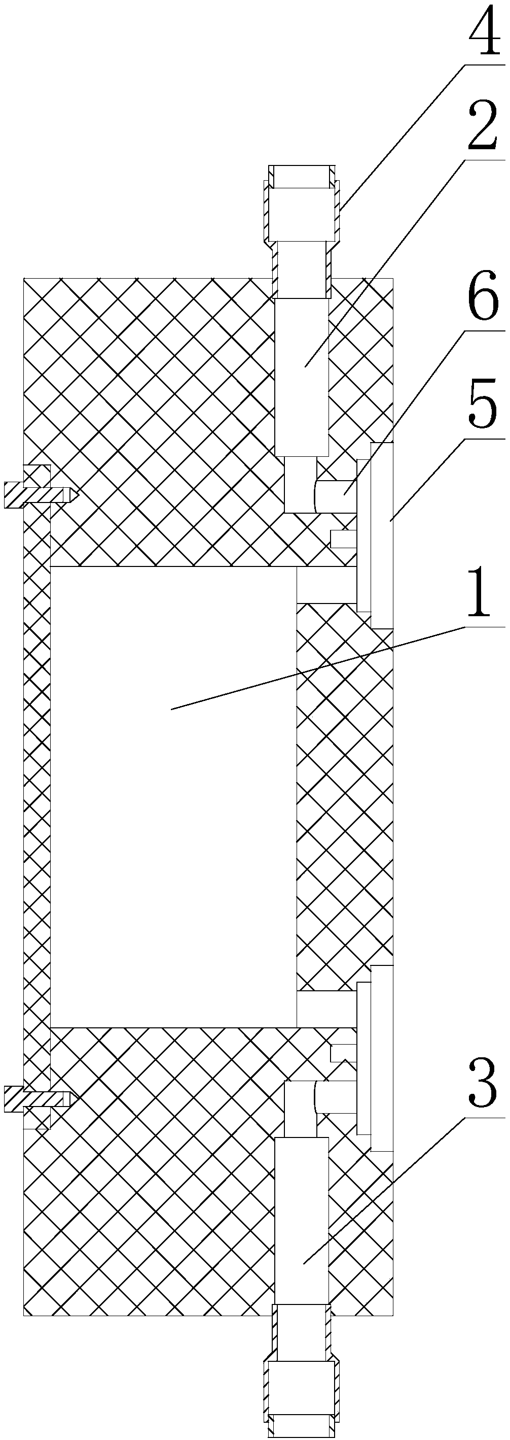
[0023] like figure 1 As shown, the cultivation fluid storage structure in the biosensor includes a liquid storage structure body and a liquid storage chamber 1 arranged on the liquid storage structure body, and the liquid storage chamber 1 is a cavity enclosed in the liquid storage structure body;

[0024] It also includes the first pipeline 2 and the second pipeline 3 arranged on the liquid storage structure body, and two accommodating chambers 5 arranged on the side of the liquid storage structure body, and the accommodating chambers 5 are all steps with a stepped surface A hole-shaped blind hole, and the end with a larger cross-sectional size of each accommodation cavity 5 is the outer end, and the hole depth direction of each accommodation cavity 5 is located in the horizontal direction;

[0025] In the horizontal direction, one of the accommodation chambers 5 is located outside the top end of the liquid storage chamber 1, and the other accommodation chamber 5 is located o...

Embodiment 2

[0031] like figure 1 As shown, this embodiment is further limited on the basis of Embodiment 1: the top end of the first pipeline 2 and the bottom end of the second pipeline 3 are both equipped with quick connectors 4 for air source pipes. In this solution, by setting the gas source pipe quick connector 4 on the two pipelines, when in use, the corresponding fluid pipe adopts the hose method, so that the gas source pipe and the upper gas source pipe can be quickly removed when the liquid storage chamber 1 enters the liquid. The connection of joint 4 is to realize pressure equalization and complete the connection between the cultivation liquid pipe and the quick joint 4 of the lower air source pipe to facilitate liquid intake; It is used to introduce purge gas into the liquid storage chamber 1, and replace the hose on the quick connector 4 of the lower gas source pipe with a waste liquid pipe for waste liquid diversion.

[0032]In order to make this solution adaptable to hoses ...


PUM


Abstract

The invention discloses a cultivating liquid storage structure of a biosensor. The cultivating liquid storage structure comprises a liquid storage structure body and a liquid storage chamber, and further comprises a first pipeline, a second pipeline and two accommodating cavities, wherein the liquid storage chamber is arranged on the liquid storage structure body; the first pipeline and the secondpipeline are arranged on the liquid storage structure body; the two accommodating cavities are formed in the side surface of the liquid storage structure; in the horizontal direction, one accommodating cavity is positioned in the outer side of the top end of the liquid storage chamber, the other accommodating cavity is positioned in the outer side of the bottom end of the liquid storage chamber,and the accommodating cavities are both circular blind holes; each of the first pipeline and the second pipeline comprises two horizontal sections and one vertical section; the axial direction of eachhorizontal section is positioned in the horizontal direction; the axial direction of each vertical section is positioned in the vertical direction. The structure has the characteristics of convenience in change of liquid in the liquid storage chamber.

Description

technical field [0001] The invention relates to the technical field of detection instruments, in particular to a culture fluid storage structure in a biosensor. Background technique [0002] A biosensor is an instrument that is sensitive to biological substances and converts its concentration into an electrical signal for detection. It is made of immobilized biosensitive materials as recognition elements (including enzymes, antibodies, antigens, microorganisms, cells, tissues, nucleic acids and other biologically active substances), appropriate physical and chemical transducers (such as oxygen electrodes, photosensitive tubes, field effect tubes, Piezoelectric crystals, etc.) and an analysis tool or system composed of a signal amplification device. [0003] Biosensors are widely used in environmental quality analysis, but most of the existing biosensors are laboratory products, which require manual liquid addition, drainage and cleaning. The operation process is cumbersome...

Claims


Application Information

Patent Timeline
IPC IPC(8): G01N33/48G01N27/00
CPCG01N27/00G01N33/48
Inventor 何平
Owner 重庆晓微城企业孵化器有限公司
Why Eureka
Try Eureka