Motor rotation shaft and processing method thereof

A technology of motor shaft and processing method, which is applied in the manufacture of motor generators, electrical components, electromechanical devices, etc., can solve problems such as easy deformation and affect normal power output, and achieve the effect of increasing stability

Inactive Publication Date: 2018-05-25
JIANGYIN YONGXING MACHINERY MFG
View PDF4 Cites 3 Cited by
  • Summary
  • Abstract
  • Description
  • Claims
  • Application Information

AI Technical Summary

Problems solved by technology

[0003] The purpose of the present invention is to provide a motor shaft and its processing method to solve the problem that the original motor sh

Method used


Image

  • Motor rotation shaft and processing method thereof
  • Motor rotation shaft and processing method thereof
  • Motor rotation shaft and processing method thereof

Examples


Embodiment Construction

[0022] The following will clearly and completely describe the technical solutions in the embodiments of the present invention with reference to the accompanying drawings in the embodiments of the present invention. Obviously, the described embodiments are only some, not all, embodiments of the present invention. Based on the embodiments of the present invention, all other embodiments obtained by persons of ordinary skill in the art without making creative efforts belong to the protection scope of the present invention.

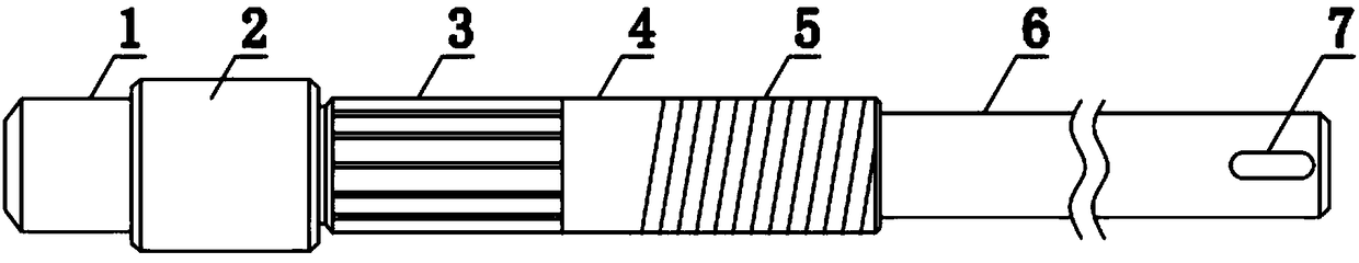
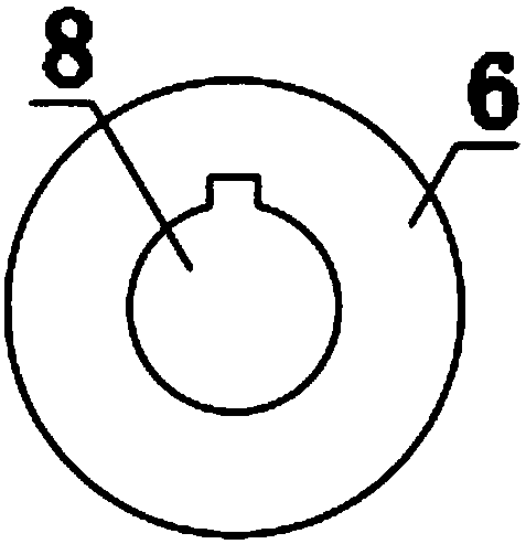
[0023] see Figure 1-3 , the present invention provides a technical solution: a motor shaft, including a journal 1, the right end of the journal 1 is connected with a limit shaft 2, the right end of the limit shaft 2 is connected with a bearing shaft 4, and the load shaft 4 The left end of the outer wall is uniformly and horizontally provided with an iron core clamping groove 3, and the right side of the outer wall of the bearing shaft 4 is provided with a pos...


PUM

PropertyMeasurementUnit
Melting temperatureaaaaaaaaaa

Abstract

The invention discloses a motor rotation shaft in the technical field of a motor rotation shaft. The motor rotation shaft comprises a shaft neck. The right end of the shaft neck is connected with a limit shaft lever; the right end of the limit shaft lever is connected with a bearing shaft lever; the left end of the outer wall of the bearing shaft lever is uniformly and transversely provided with iron core clamping grooves; the right side of the outer wall of the bearing shaft lever is provided with positioning threads; and the right end of the bearing shaft lever is connected with an output shaft lever. The processing method of the motor rotation shaft has the following steps: S1) casting moulding; S2) annealing processing; S3) profile machining; S4) finish machining; S5) carburization; and S6) annealing and tempering. Through arrangement of the iron core clamping grooves and the positioning threads, the motor rotation shaft can carry out positioning on an iron core and a coil of a rotor, thereby preventing movement phenomenon during use, and increasing motor stability; and through processing of the motor rotation shaft, the motor rotation shaft is allowed to be higher in strengthand better in external flexibility.

Description

technical field [0001] The invention relates to the technical field of motor shafts, in particular to a motor shaft and a processing method thereof. Background technique [0002] The motor consists of two parts, the rotor and the stator, which are used to realize the conversion of electrical energy and mechanical energy and mechanical energy and electrical energy. The motor rotor is divided into a motor rotor and a generator rotor. The iron core and coil of the motor are installed on the motor shaft, and positioning needs to be performed during installation. When the original motor shaft is in use, it is prone to deformation due to external forces. affect the normal power output, for this reason, we propose a motor shaft and its processing method. Contents of the invention [0003] The purpose of the present invention is to provide a motor shaft and its processing method to solve the problem that the original motor shaft proposed in the above background technology is easi...

Claims


Application Information

Patent Timeline
IPC IPC(8): H02K7/00H02K15/00B23P15/14
CPCH02K7/003B23P15/14H02K15/00
Inventor 陈永兴陈斌陈丽
Owner JIANGYIN YONGXING MACHINERY MFG
Why Eureka
Try Eureka