Double-surrounding rotating structure, double-surrounding tube rotating structure, integrated tube rotating structure, snake bone for medical endoscope and endoscope
A rotating structure and endoscope technology, applied in the direction of endoscope, application, medical science, etc., can solve the problems of limited service life, high time and labor costs, high cost, etc., to achieve cost control and reduce cross-infection Problems, the effect of security improvement
- Summary
- Abstract
- Description
- Claims
- Application Information
AI Technical Summary
Problems solved by technology
Method used
Image
Examples
Embodiment 1
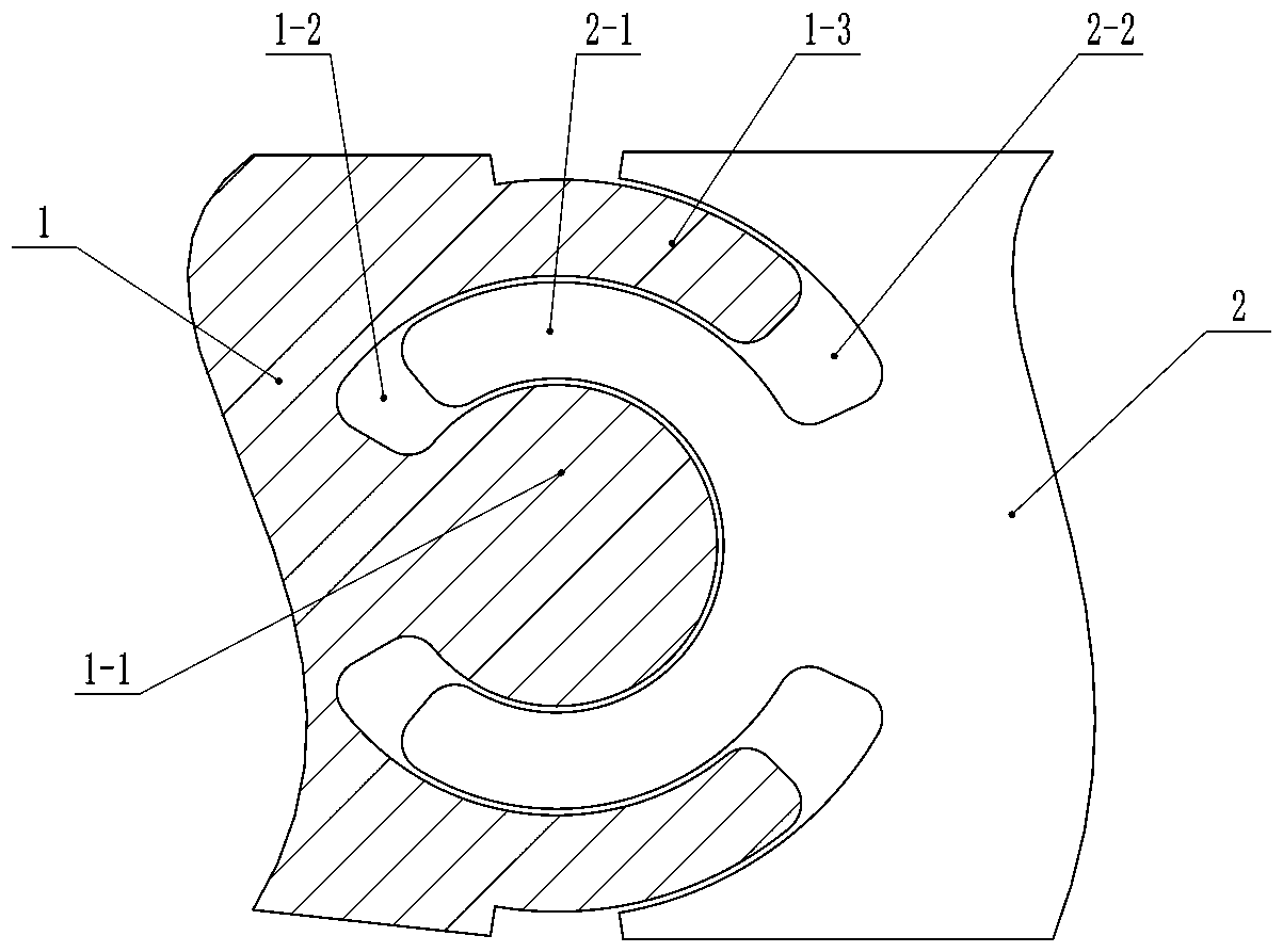
[0050] Such as figure 1 and Picture 1-1 As shown, a double-encircled rotating structure includes a female rotating part 1 and a sub rotating part 2,
[0051] The female rotating part 1 includes a circular protrusion 1-1, an inner surrounding annular groove 1-2 arranged around the circular raised part, and an outer surrounding annular protrusion arranged around the inner surrounding annular groove 1-2. Starting part 1-3;
[0052] The sub-rotating part 2 includes an inner ring-shaped raised portion 2-1 for surrounding the circular raised portion 1-1 and an outer ring-shaped groove arranged around the inner ring-shaped raised portion 2-1. 2-2;
[0053] The inner ring-encircling protruding part 2-1 of the sub-rotating part 2 is arranged in the inner ring-encircling groove 1-2 of the female rotating part 1, and the outer encircling ring-shaped protruding part 1-3 of the female rotating part 1 It is arranged in the outer ring-shaped groove 2-2 of the sub-rotating part 2, and ma...
Embodiment 2
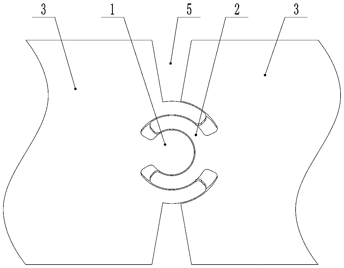
[0057] Such as diagram 2-1 , Figure 2-2 and figure 1 As shown, the difference between this embodiment and Embodiment 1 is: a double-encircling pipe body rotation structure, including two pipe bodies 3, and the circumferential sides of the connecting ends of the two pipe bodies 3 respectively pass through the double pipe body. The embracing and rotating structure is connected, and the rotation axes of the double embracing and rotating structures on both sides are coaxially arranged. Specifically, two female rotating parts 1 are respectively located on both sides of the connecting end of one of the pipes, and two female rotating parts 1 are formed on both sides of the connecting end of the other pipe. There are two sub-rotating parts 2 on both sides, and the other two sides in the circumferential direction of the connecting ends of the pipe body 3 in the two sections respectively have an axial opening 4;
[0058] The axial openings 4 of the two sections of the tube body 3 re...
Embodiment 3
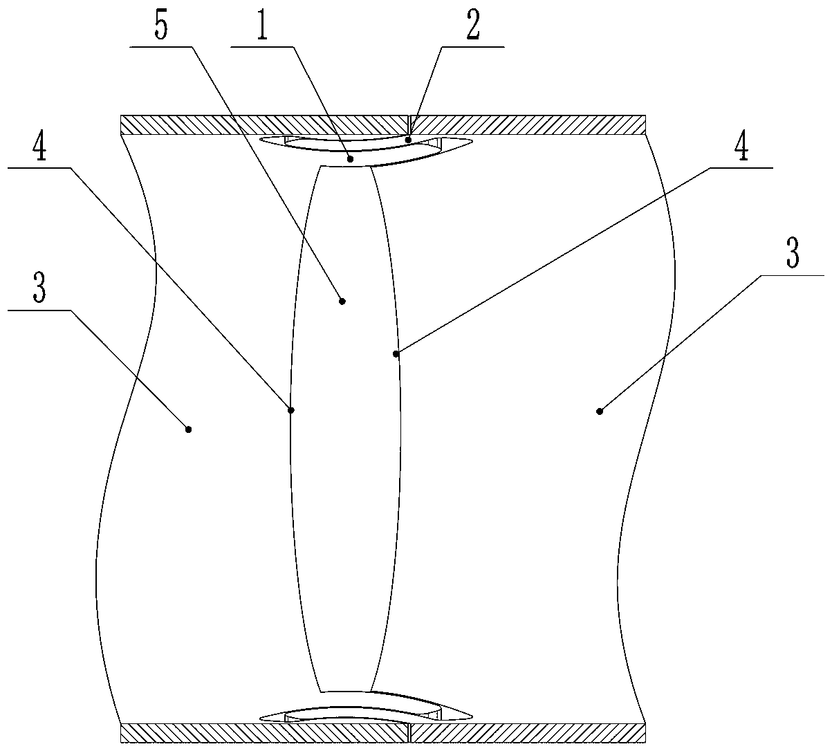
[0063] Such as image 3 As shown, the difference between this embodiment and embodiment 2 is: an integrated tubular body rotating structure, which includes the double-encircling tubular body rotating structure,
[0064] The rotating contact surface of the female rotating part 1 and the sub rotating part 2 is a radial limit bevel 6, and the inclination directions of the radial limit bevels in the two double-encircling tubular body rotating structures on both sides are opposite, so that To prevent radial disengagement of the pipe body 3 described in the two sections, due to the adoption of an integrated structure, the integrated structure is formed at one time without assembly process, which saves the production process, reduces time cost and labor cost.
[0065] Principle: During the cutting process, the laser cutting beam always points to the center of the pipe body, and every slit on the circumference has an angle. As long as the thickness of the stainless steel pipe wall is ...
PUM
 Abstract
Description
Claims
Application Information
 - R&D
- Intellectual Property
- Life Sciences
- Materials
- Tech Scout
- Unparalleled Data Quality
- Higher Quality Content
- 60% Fewer Hallucinations
Browse by: Latest US Patents, China's latest patents, Technical Efficacy Thesaurus, Application Domain, Technology Topic, Popular Technical Reports.
© 2025 PatSnap. All rights reserved.Legal|Privacy policy|Modern Slavery Act Transparency Statement|Sitemap|About US| Contact US: help@patsnap.com


