Device and method for tightening front nuts of high-pressure rotor sealing disc of aero-engine

An aero-engine, high-pressure rotor technology, applied in metal processing, metal processing equipment, manufacturing tools, etc., can solve the problems of small tightening space, inability to ensure the consistency of nut tightening, long tightening transmission distance, etc., to ensure the tightening torque and angle. Accuracy, reduce skill requirements and labor intensity, reduce the effect of tightening transmission distance

Active Publication Date: 2018-05-29
DALIAN UNIV OF TECH
View PDF6 Cites 6 Cited by
  • Summary
  • Abstract
  • Description
  • Claims
  • Application Information

AI Technical Summary

Problems solved by technology

The size of the space occupied by the internal tightening of the high-pressure rotor varies depending on the engine model, but they all have the characteristics of narrow and long space layout. Among them, the axial depth of the nut relative to the rear shaft port of the high-pressure turbine rotor reaches 600-800mm, and the distance between the nut and the rear shaft of the high-pressure turbine rotor The inner diameter of the channel is φ100-150mm, the inner diameter of the inner ring of the sealing disc is 100-200mm, the distribution diameter of the nuts is φ250-400mm, the axial distance between the last stage disc of the high-pressure compressor and the sealing disc is less than 100mm, and there are air ducts, etc. The space interference assembly, in which the air duct protrudes 10-20mm from the rear end face of the last stage of the high-pressure compressor, has difficulties such as long feed channel, difficulty in unfolding the tightening lever, small tightening space and multi-region interference for the operation of the tightening mechanism. Domestically, the operation of slender tightening tools is mainly used to carry out deep, deflected and tightened methods. During the process, a large number of manual operations are relied on, and automatic special tightening devices are not used. The main shortcomings are as follows: (1) Poor consistency of tightening quality: Manual operation The method of tightening the wrench in place has problems such as the offset and inclination of the nut cap, which cannot guarantee the tightening consistency of each nut, and even some nuts are wrongly screwed or missed. The overall rigidity is low, and the anti-torsion effect is poor, which leads to the deformation of the device under load during the tightening process, which affects the tightening quality; (2) Low tightening accuracy: the current application device mainly uses a human torque device or an external torque system as the tightening power input, which has the advantages of tightening The problem of long transmission distance, due to the characteristics of low rigidity, large transmission gap and large uncertainty of deformation form after loading in long-distance transmission, the actual torque and screw-in angle of the nut have a large deviation from the measured value of the remote sensor, and There are random errors that are difficult to compensate, and the nut tightening torque and rotation angle accuracy cannot be guaranteed; (3) The tightening efficiency is low: after the existing method completes the nut group capping and the first tightening, the second tightening usually requires the device to be repeatedly tightened in the high-pressure rotor It takes a lot of time to insert the installation and pull out and disassemble to complete the correct positioning of the upper sleeve relative to the nut of each angle phase of the tightening sleeve. The problem of high strength, tightening all the nuts requires multiple people to work together for more than 6 hours, the work efficiency is low, and the assembly accuracy of the whole machine is affected

Method used


Image

  • Device and method for tightening front nuts of high-pressure rotor sealing disc of aero-engine
  • Device and method for tightening front nuts of high-pressure rotor sealing disc of aero-engine
  • Device and method for tightening front nuts of high-pressure rotor sealing disc of aero-engine

Examples


Embodiment Construction

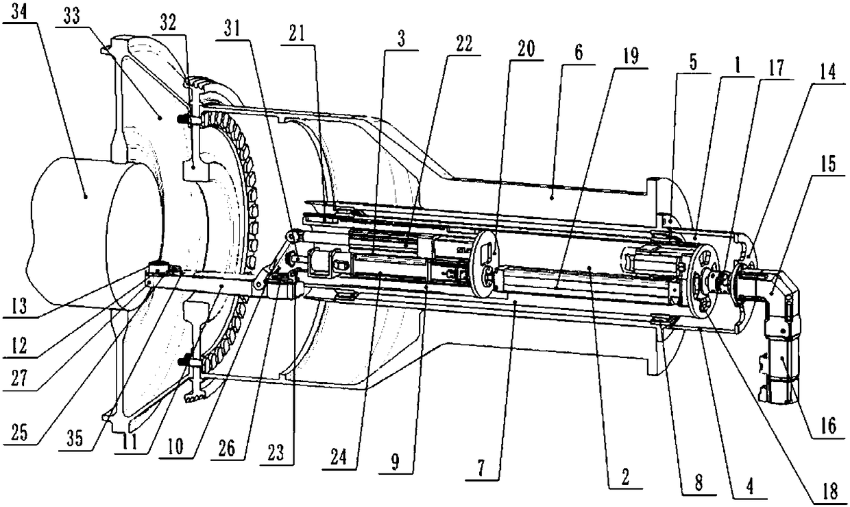
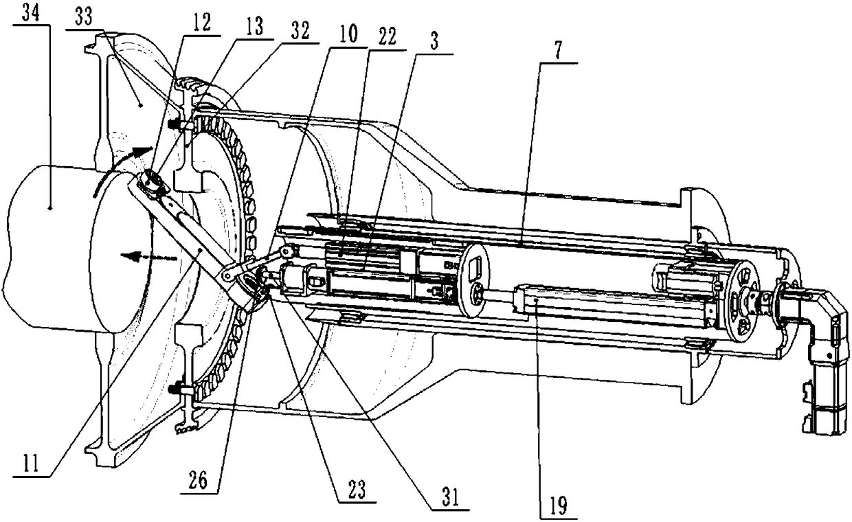
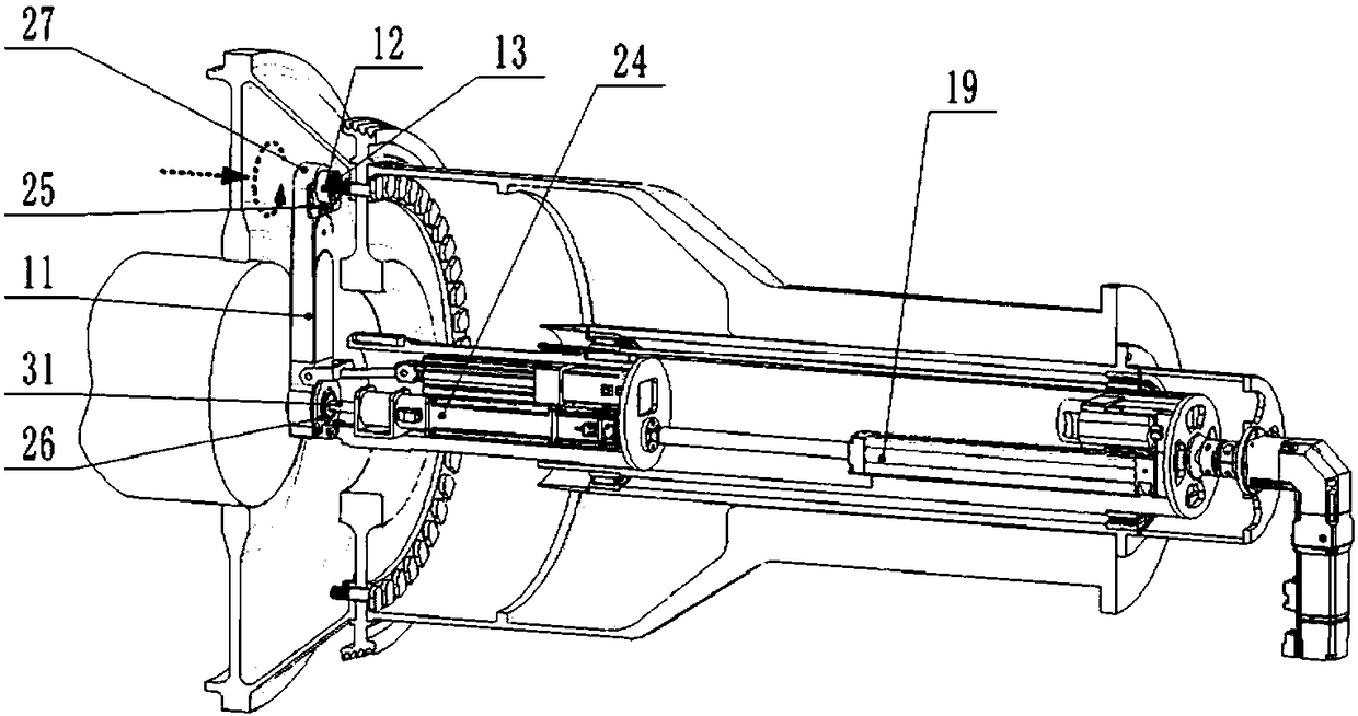
[0041] The specific embodiments of the present invention will be described in detail below in conjunction with the technical solutions and accompanying drawings. Such as Figure 1-7 As shown, a front-end nut tightening device for a high-pressure rotor sealing disc of an aeroengine includes an indexing system 1, a feed movement system 2 and a connecting rod type tightening execution system 3.

[0042] The indexing system 1 is fixedly installed on the rear shaft port of the high-pressure turbine rotor 6 through the flange 5 of the outer sleeve 4 .

[0043] The feed motion system 2 is located inside the indexing system 1, the middle sleeve 7 of the feed motion system 2 is connected with the outer sleeve 4 of the indexing system 1 through a bearing 8, and the indexing system 1 realizes the feed motion system 2 CNC turns.

[0044] The link type tightening execution system 3 is located at the front end of the feed movement system 2, and the inner sleeve 9 of the link type tighteni...


PUM


Abstract

The invention discloses a device and a method for tightening front nuts of a high-pressure rotor sealing disc of an aero-engine. The device comprises a transposition system, a feeding movement systemand a connecting rod type tightening execution system, wherein the feeding movement system is located in the transposition system and is used for achieving numerical control rotation of the feeding movement system the connecting rod type tightening execution system is located inside the feeding movement system and is used for realizing axial linear feeding movement of the connecting rod type tightening execution system, and the connecting rod type tightening execution system is used for enabling a tightening sleeve to move to a tightening station so as to tighten the nuts. According to the device and the method for tightening the front nuts of the high-pressure rotor sealing disc of the aero-engine, a numerical control operation mode is adopted, so that the steps of enabling the tighteningsleeve to move to the tightening station, making the tightening sleeve be in place, nut installation, tightening and the like are achieved, the characteristics of high in automation degree and high in movement precision are realized, manual misoperation is avoided, and tightening consistency of all the nuts is guaranteed; and a secondary tightening of a nut set is achieved by adopting the transposition system, working efficiency is improved, and the skill requirement and labor intensity of workers are reduced.

Description

technical field [0001] The invention belongs to the technical field of automatic assembly, in particular to a device and method for tightening a front nut of a high-pressure rotor sealing plate of an aero-engine. Background technique [0002] In the core machine of an aero-engine, the high-pressure rotor is mainly composed of a high-pressure compressor rotor and a high-pressure turbine rotor. The rear end face of the rotor is connected, and the three are fastened by dozens of threaded connectors uniformly distributed along the axis of the axis to realize the assembly of the main structure of the high-pressure rotor. For some models, the nuts in the threaded fasteners are sealing plate front nuts, which are located on the front side of the sealing plate, and the contact end is pressed against the rear mounting edge of the high-pressure compressor rotor. Dedicated D-shaped bolts for limit and corner locking functions. Since the high-pressure rotor is the core power component...

Claims


Application Information

Patent Timeline
Patent Type & Authority Applications(China)
IPC IPC(8): B23P19/06B23P19/04
CPCB23P19/042B23P19/06
Inventor 高航周天一
Owner DALIAN UNIV OF TECH
Why Eureka
Try Eureka