An automatic nailing machine for an optical cable reel

An automatic, fiber optic cable technology, applied in the direction of nailing tools, staple nailing tools, manufacturing tools, etc., can solve the problems of high labor intensity, long time consumption, and large volume of the whole wooden plate, so as to reduce the labor intensity of manpower and improve Work efficiency, simple and compact structure

Active Publication Date: 2020-06-16
YANGTZE OPTICAL FIBRE & CABLE CO LTD
View PDF3 Cites 0 Cited by
  • Summary
  • Abstract
  • Description
  • Claims
  • Application Information

AI Technical Summary

Problems solved by technology

[0002] At present, the sealing operation of optical cable reels is basically done manually, and the existing optical cable reels are all wooden reels, which are large in size, very heavy in weight, long in operation time and high in labor intensity.
In addition, because the specifications of the sealing plate are uniform, the last sealing plate will need to be cut again when manually sealing plates of different specifications, which takes a long time and reduces the work efficiency.

Method used


Image

  • An automatic nailing machine for an optical cable reel
  • An automatic nailing machine for an optical cable reel

Examples


Embodiment Construction

[0021] The present invention will be described in detail below in conjunction with the accompanying drawings and embodiments.

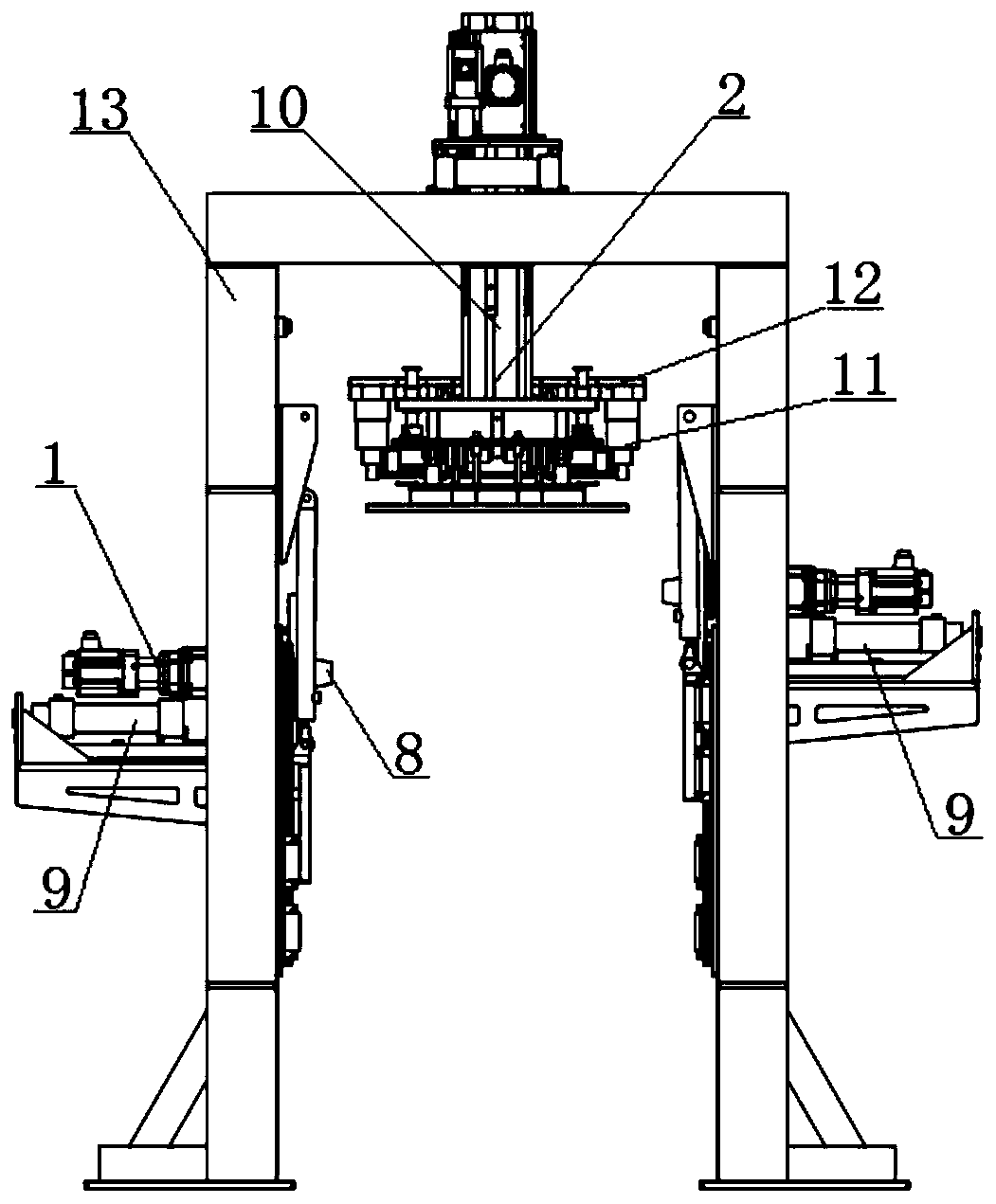
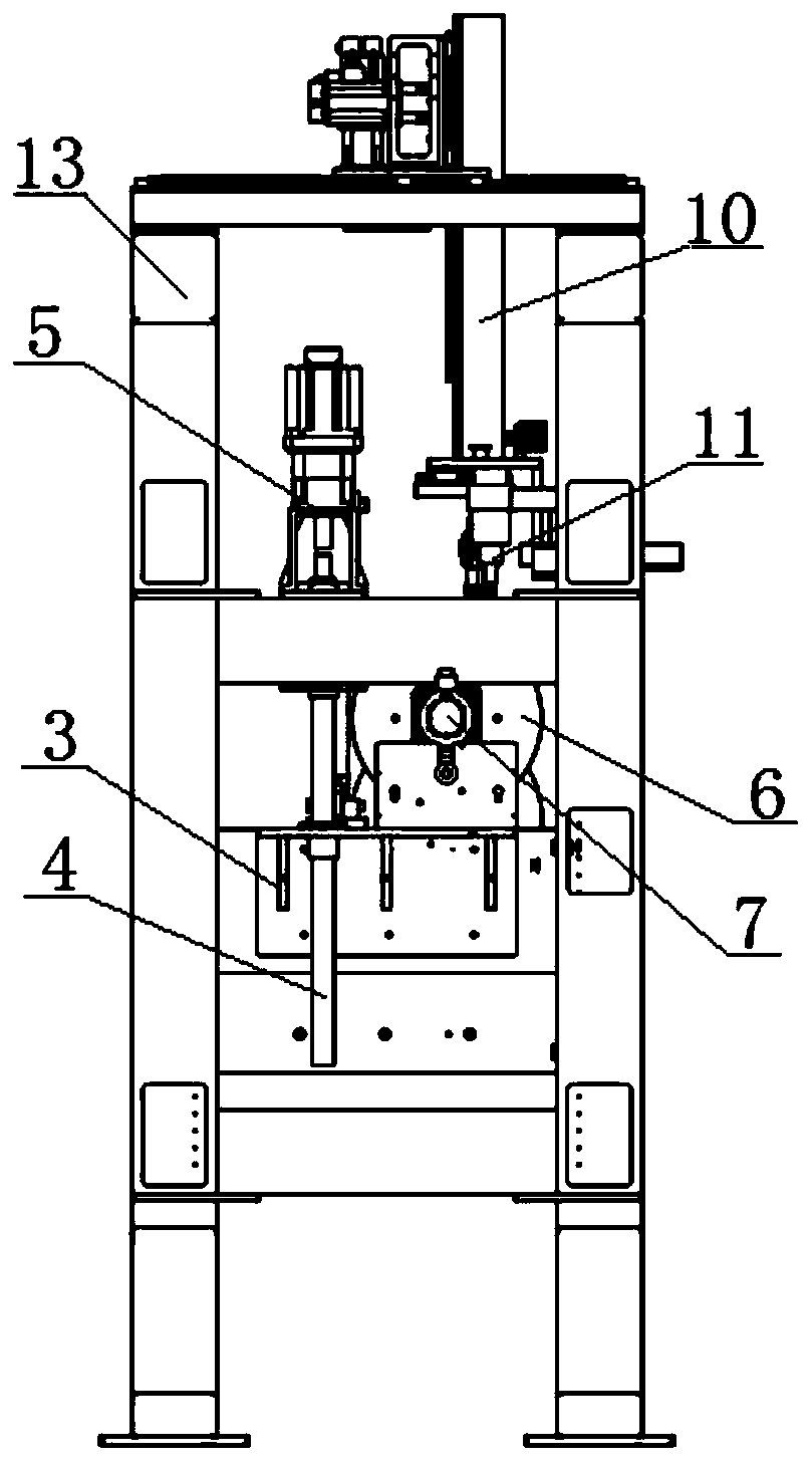
[0022] refer to Figure 1 ~ Figure 2 As shown, the automatic nailing machine for optical cable reels in an embodiment provided by the present invention includes a frame 13, a lifting and rotating mechanism 1 and a nailing and plate mechanism 2, and the lifting and rotating mechanism 1 includes two lifting devices, which are symmetrically arranged on the machine. On both sides of the frame 13, each lifting device is provided with a rotating device. The lifting device drives the rotating device to move up and down. The disk rotates, and the nail plate mechanism 2 is arranged on the top of the frame 13. The nail plate mechanism 2 includes a nail plate gun 11; the lifting and rotating mechanism 1 clamps the optical cable disk from both sides through the chuck 8, and the lifting device lifts the optical cable disk to the nail plate. Below the plate gun 11...


PUM


Abstract

The invention discloses an automatic board nailing machine for cable trays. The automatic board nailing machine comprises a machine frame, a lifting rotary mechanism and a board nailing mechanism. Thelifting rotary mechanism comprises two lifting devices. The lifting devices are symmetrically arranged at the two sides of the machine frame. Each lifting device is provided with a rotating device. The lifting devices drive the corresponding rotating devices to move up and down. The rotating devices are provided with chucks. The rotating devices can clamp the cable trays from the two sides through the corresponding chucks and further drive the cable trays to rotate. The board nailing mechanism is arranged at the top of the machine frame and further comprises a board nailing gun. The cable trays of different specifications can be automatically nailed. The structure is simple and compact, working efficiency is improved, the number of workers is decreased, the labor intensity is relieved andthe cable trays can be nailed quickly and intelligently.

Description

technical field [0001] The invention relates to the technical field of optical cable equipment, in particular to an automatic nailing machine for optical cable reels. Background technique [0002] The sealing operation of the current optical cable reels is basically all done manually, and the existing optical cable reels are all wooden reels, which are large in volume, very heavy in weight, long in operation time and high in labor intensity. In addition, because the specifications of the sealing boards are uniform, the last sealing board needs to be cut again when manually sealing dishes of different specifications, which takes a long time and reduces the working efficiency. The sealing problem of optical cable reels is a pain point and bottleneck problem in the optical cable industry. Contents of the invention [0003] The technical problem to be solved by the present invention is to provide an automatic nailing machine for optical cable reels to realize the automatic na...

Claims


Application Information

Patent Timeline
Patent Type & Authority Patents(China)
IPC IPC(8): B27F7/02B27M3/00
CPCB27F7/02B27M3/0073
Inventor 杜家佳黄杰陈锋聂鹏飞曹首科汤大刚赵帅
Owner YANGTZE OPTICAL FIBRE & CABLE CO LTD
Why Eureka
Try Eureka