Eureka AIR delivers breakthrough ideas for toughest innovation challenges, trusted by R&D personnel around the world.

Vertical take-off and landing aircraft with layouts of tilting ducts and connecting wings

A technology of vertical take-off and landing and connecting wings, applied in the field of unmanned aerial vehicles, it can solve the problems of inability to trim the pitching moment, the aircraft cannot maintain the vertical attitude, etc. Practical effect

Inactive Publication Date: 2018-05-29
BEIHANG UNIV
View PDF15 Cites 17 Cited by
  • Summary
  • Abstract
  • Description
  • Claims
  • Application Information

AI Technical Summary

Problems solved by technology

As announced by the notification number CN106167096A, a kind of improved approximate horizontal rotation propeller flap increases the connecting wing aircraft, all the ducted propellers are arranged on the leading edge of the front wing, and the tail only has a trim fan in the opening of the fuselage , the leading edge fan will generate pitching moment that cannot be trimmed during vertical take-off and landing, so that the vertical attitude of the aircraft cannot be maintained

Method used


Image

  • Vertical take-off and landing aircraft with layouts of tilting ducts and connecting wings
  • Vertical take-off and landing aircraft with layouts of tilting ducts and connecting wings
  • Vertical take-off and landing aircraft with layouts of tilting ducts and connecting wings

Examples


Embodiment Construction

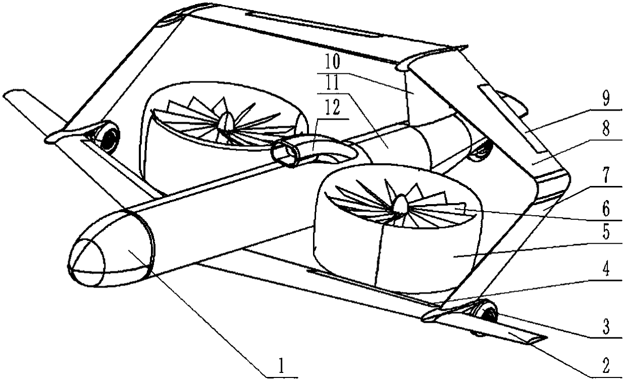
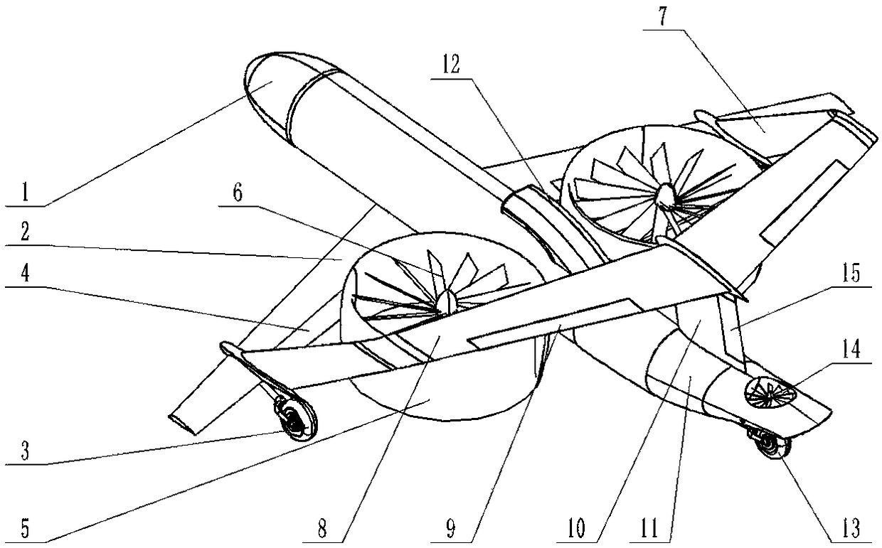
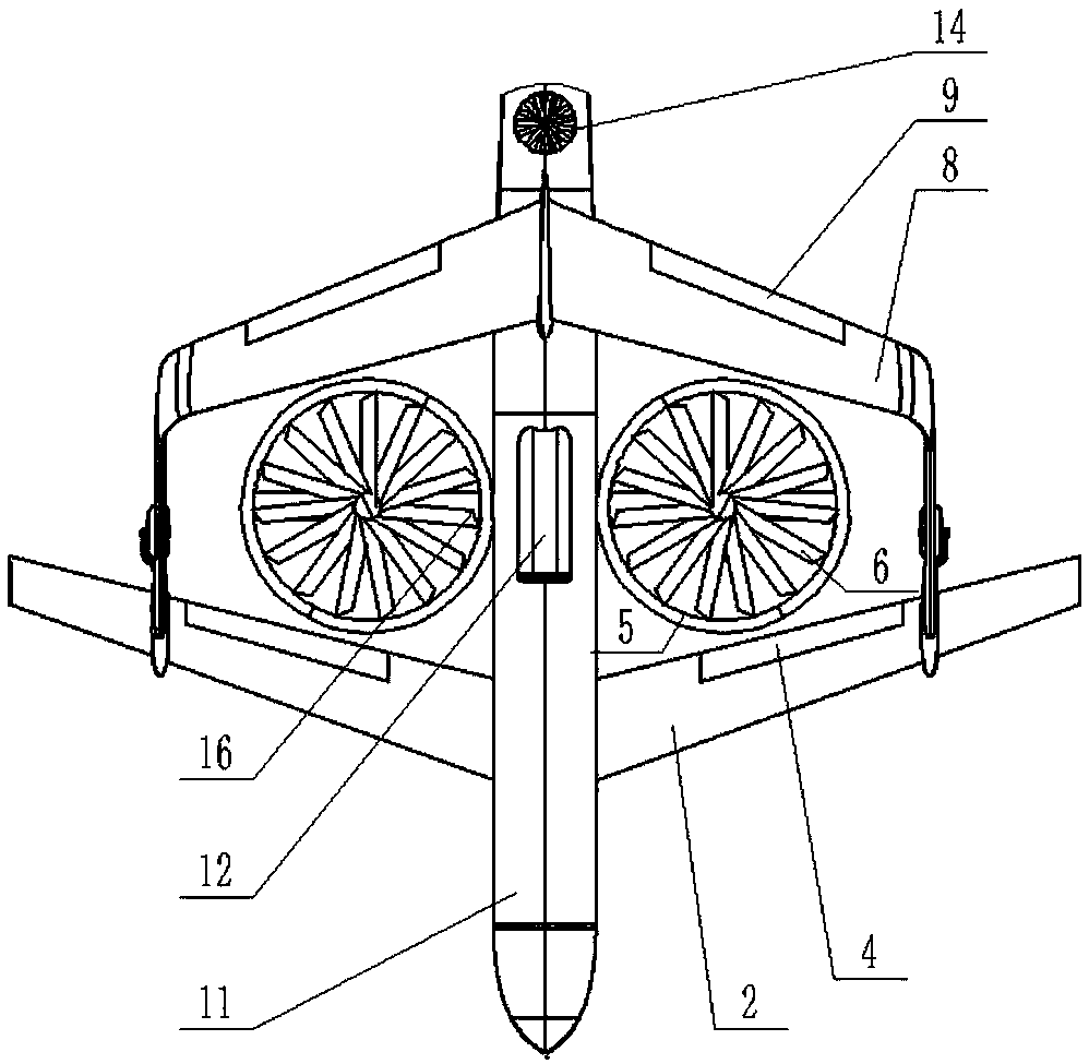
[0030] Such as figure 1 As shown in , an aircraft with vertical take-off and landing with a tilting ducted fan connected to the wing layout, such as Figure 1-Figure 5As shown, the aircraft includes a fuselage 1, connecting wings 2, tilting ducted fans, tail trim fans 14 and landing gear. The connecting wing includes a front wing 2 and a rear wing 8, and there is a certain height difference between the two wings and different distances from the nose along the direction of the fuselage, forming a staggered arrangement in space. The root of the rear wing is connected to the rear of the fuselage by a vertical empennage 10, and the tip of the rear wing is connected to the middle part of the front wing 2 through a vertical connection structure 7. The tilting ducted fan is composed of the main duct 5 and the main fan 6, and is arranged in the middle of the fuselage, avoiding the vertical projection area of ​​the connecting wing, and symmetrically arranged left and right. The engin...


PUM


Abstract

The invention discloses a vertical take-off and landing aircraft with layouts of tilting ducts and connecting wings. The vertical take-off and landing aircraft comprises a fuselage, tilting duct fans,the connecting wings, undercarriages and an empennage trim fan. The connecting wings are divided into the front wings and the rear wings; the tilting duct fans are arranged in a bilateral symmetry mode and connected with the middle of the fuselage through tilting structures, and an engine arranged inside the fuselage drives the tilting duct fans through transmission mechanisms arranged in the tilting structures so that upward lift force or forward thrust can be provided for the aircraft; the front wing faces and the rear wing faces of the connecting wing structures have the height difference,wing roots of the rear rings are connected to a vertical empennage, wing tips of the rear wings are connected to the middle sections of the front wings, and full-aircraft lift force is provided at the flat flight stage; and the layout of the tilting duct fans and the layout of the connecting wings are combined, and the wing structures are complete. The vertical take-off and landing aircraft can take off and land vertically and hover in the air and can also take off and land in a sliding mode and cruise at a high speed like a fixed wing aircraft; the duct fan propelling mode is quiet and efficient, and the engine is mounted inside the fuselage; and the aircraft overall layout is compact and reasonable, a transmission device is precise and simple, safety and reliability are achieved, and thus high application value is achieved.

Description

technical field [0001] The invention relates to a vertical take-off and landing unmanned aerial vehicle with a tilting double-duct connecting wing layout, and belongs to the technical field of unmanned aerial vehicle of aviation vehicle technology. Background technique [0002] Tilt-rotor vertical take-off and landing fixed-wing aircraft has both vertical take-off and landing capabilities and horizontal flight capabilities. It is mainly used in complex take-off and landing environments lacking airport support, and has rapid task response capabilities. [0003] At present, the existing thrust-oriented vertical take-off and landing fixed-wing UAVs use multi-rotor systems to provide the pulling force during the vertical take-off and landing stage, and switch to another power system during the level flight stage. The mass of the aircraft is mostly below 80kg, and the payload is 6kg. the following. For example, a fixed-wing unmanned aerial vehicle with vertical take-off and land...

Claims


Application Information

Patent Timeline
IPC IPC(8): B64C27/26B64C27/28B64C29/00B64C39/08
CPCB64C27/26B64C27/28B64C29/0033B64C39/08B64U10/25B64U30/20B64U50/14
Inventor 马铁林王祥胜别大卫张秦岭
Owner BEIHANG UNIV
Why Eureka
Eureka Blog
Learn More