

Sample pretreatment device and method for tinplate alloy-tin couple test
A technology for sample pretreatment and tin galvanic coupling, which is applied in the preparation of test samples, measuring devices, electrolysis process, etc., and can solve the problems of difficult to master the method, complicated operation, poor sample pretreatment effect, etc.
- Summary
- Abstract
- Description
- Claims
- Application Information
AI Technical Summary
Problems solved by technology
Method used
Image

Examples
Embodiment Construction
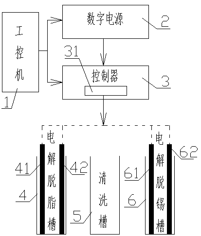
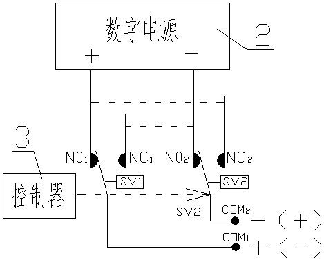
[0022] Example figure 1 As shown, the sample pretreatment device of the tinplate alloy-tin galvanic couple test of the present invention comprises an industrial computer 1, a digital power supply 2, a controller 3, an electrolytic degreasing tank 4, a cleaning tank 5 and an electrolytic tin removal tank 6. The output terminals of the machine 1 and the digital power supply 2 are respectively connected to the input terminals of the controller 3, the electrolytic degreasing tank 4 is provided with auxiliary plates 41 and samples 42 at intervals, and the electrolytic detinning tank 6 is provided with cathodes 61 at intervals and sample 62, the controller 3 is provided with a polarity changeover switch 31, the input end of the polarity changeover switch 31 is connected to the output end of the digital power supply 2, and the output end is respectively connected to the auxiliary parts of the electrolytic degreasing tank 4. The electrode plate 41 and the sample 42 as well as the cath...
PUM
 Abstract
Description
Claims
Application Information