Damping hinge for furniture

A technology for damping hinges and furniture, which is applied to hinges with pins, door/window accessories, hinges, etc. It can solve the problems of large size of the hinge body, low service life of the damper, and increased manufacturing costs of the hinge. Simple and reasonable, high damper life and low manufacturing cost

Inactive Publication Date: 2018-05-29
刘荣康
View PDF0 Cites 2 Cited by
  • Summary
  • Abstract
  • Description
  • Claims
  • Application Information

AI Technical Summary

Problems solved by technology

[0002] Hinges are commonly used connectors in furniture, especially the use of dampers in furniture hinges, which increases the stability and flexibility of the hinges. However, a defect in a large number of known damping hinge technologies for furniture is that , since the damper is generally set in the middle abdomen of the connecting arm, that is, the cavity between the connecting arm and the adjustment base fitting, in order to facilitate the movement and function adjustment of the damper, the cavity should be large enough so that the hinge body has a relatively small volume Large, which increases the manufacturing cost of the hinge and reduces the use space of the cabinet; and the damper is generally a pull-out damper, that is, the damper only has a damping function when the piston rod is pulled out; and the existing hinge with a damper The life of the damper in the

Method used


Image

  • Damping hinge for furniture
  • Damping hinge for furniture
  • Damping hinge for furniture

Examples


Embodiment 1

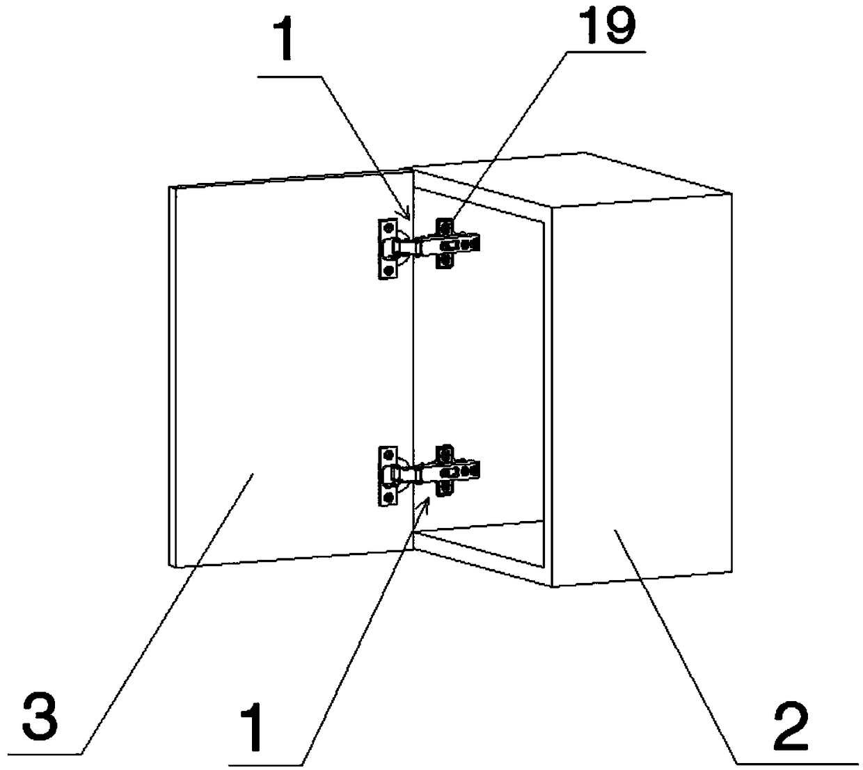
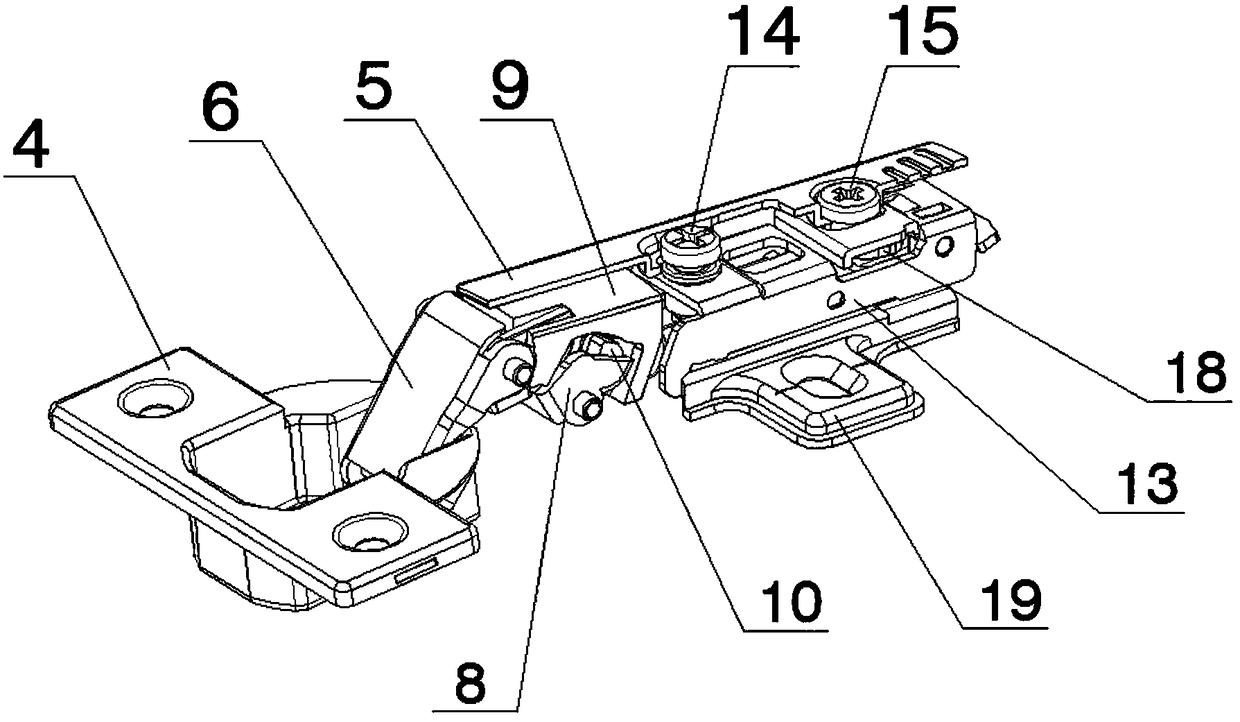
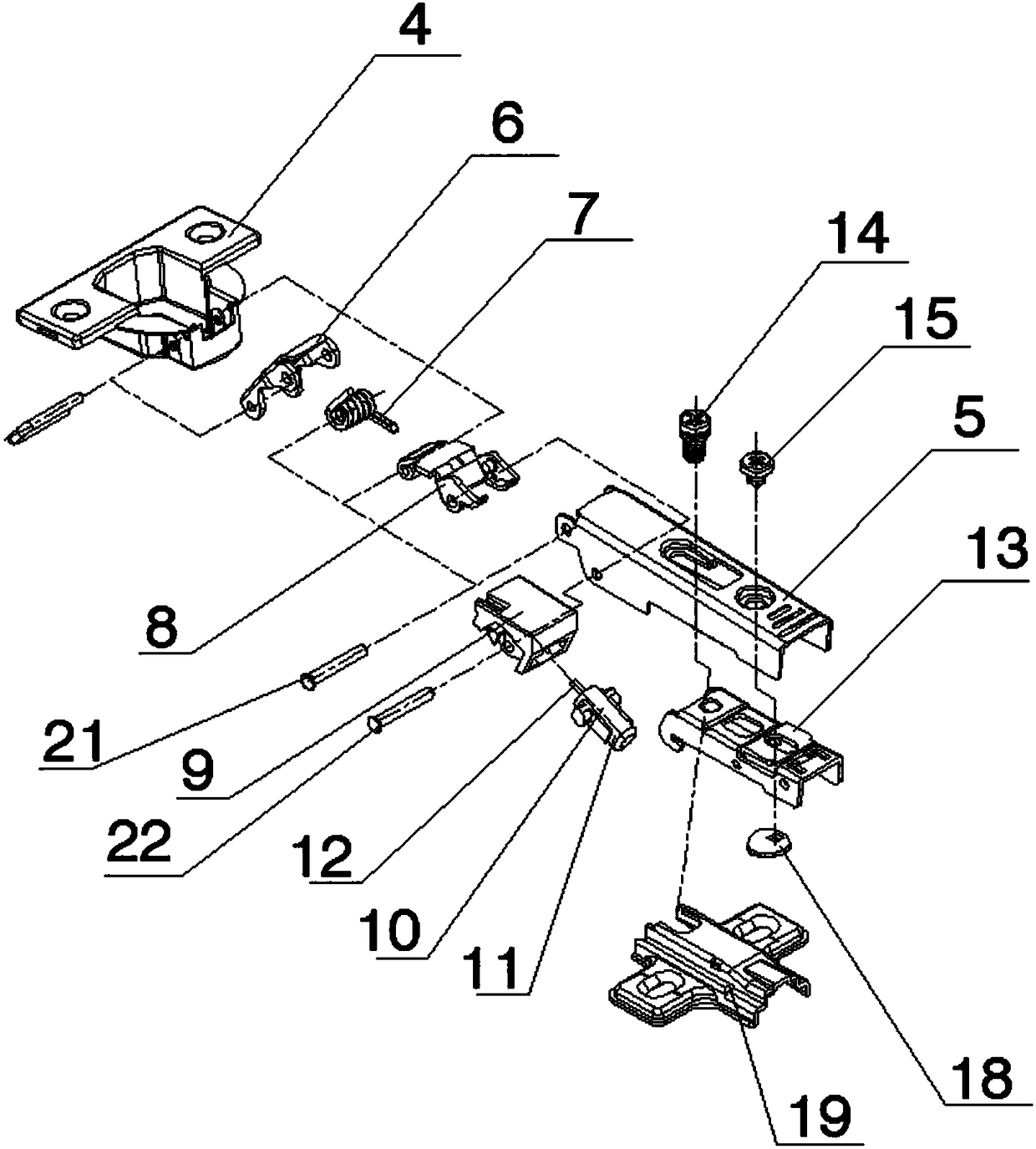
[0037] A damping hinge for furniture (see Figure 2-Figure 9 ), including a movable cup holder 4, a fixed seat 19 connected to the movable cup holder 4 through the connecting arm 5, and an outer rocker arm 6, an inner rocker arm 8 and a base are installed between the movable cup holder 4 and the connecting arm 5 seat 9; one end of the outer rocker arm 6 and one end of the inner rocker arm 8 are respectively installed in the cup groove of the movable cup seat 4 through a shaft; the other end of the outer rocker arm 6 is connected with the connecting arm 5 through the first pin shaft 21, And the spring 7 is installed on the first pin shaft 21; the base 9 is connected with the inner rocker arm 8 through the second pin shaft 22, and the two ends of the second pin shaft 22 are installed on the connecting arm 5; the base 9 has a cavity, and the cavity of the base 9 is composed of a top plate 9.3, a bottom plate 9.2, a front plate 9.4, a back plate 9.1 and a side wall 9.5, and the bo...

Embodiment 2

[0046] A damping hinge for furniture (see Figure 2-Figure 9 ), including a movable cup holder 4, a fixed seat 19 connected to the movable cup holder 4 through the connecting arm 5, and an outer rocker arm 6, an inner rocker arm 8 and a base are installed between the movable cup holder 4 and the connecting arm 5 seat 9; one end of the outer rocker arm 6 and one end of the inner rocker arm 8 are respectively installed in the cup groove of the movable cup seat 4 through a shaft; the other end of the outer rocker arm 6 is connected with the connecting arm 5 through the first pin shaft 21, And the spring 7 is installed on the first pin shaft 21; the base 9 is connected with the inner rocker arm 8 through the second pin shaft 22, and the two ends of the second pin shaft 22 are installed on the connecting arm 5; the base 9 has a cavity, and the cavity of the base 9 is composed of a top plate 9.3, a bottom plate 9.2, a front plate 9.4, a back plate 9.1 and a side wall 9.5, and the bo...

Embodiment 3

[0050] A damping hinge for furniture (see Figure 2-Figure 9 ), including a movable cup holder 4, a fixed seat 19 connected to the movable cup holder 4 through the connecting arm 5, and an outer rocker arm 6, an inner rocker arm 8 and a base are installed between the movable cup holder 4 and the connecting arm 5 seat 9; one end of the outer rocker arm 6 and one end of the inner rocker arm 8 are respectively installed in the cup groove of the movable cup seat 4 through a shaft; the other end of the outer rocker arm 6 is connected with the connecting arm 5 through the first pin shaft 21, And the spring 7 is installed on the first pin shaft 21; the base 9 is connected with the inner rocker arm 8 through the second pin shaft 22, and the two ends of the second pin shaft 22 are installed on the connecting arm 5; the base 9 has a cavity, and the cavity of the base 9 is composed of a top plate 9.3, a bottom plate 9.2, a front plate 9.4, a back plate 9.1 and a side wall 9.5, and the bo...


PUM


Abstract

The invention relates to a damping hinge for furniture. The damping hinge for the furniture comprises a movable cup base and a fixed base connected with the movable cup base through a connection arm.An outer rocker arm, an inner rocker arm and a substrate are installed between the movable cup base and the connection arm. One end of the outer rocker arm is in shaft connection with the connection arm through a first hinge pin, and the first hinge pin is provided with a spring. The substrate is connected with the inner rocker arm through a second hinge pin, and the inner rocker arm and the substrate are buckled and covered with the connection arm. The substrate is provided with a cavity. A damper is arranged in the cavity of the substrate. An adjusting base is arranged between the front endof the connection arm and the fixed base. The connection arm is in adjustable connection with the adjusting base through a first screw. The connection arm and the adjusting base are further provided with a second screw, an adjusting base accessory is arranged between the adjusting base and the fixed base, and the adjusting base accessory is arranged on the second screw. The damping hinge has the beneficial effects of being simple in structure and stable in connection.

Description

technical field [0001] The invention relates to a furniture hinge, in particular to a damping hinge for furniture. Background technique [0002] Hinges are commonly used connectors in furniture, especially the use of dampers in furniture hinges, which increases the stability and flexibility of the hinges. However, a defect in a large number of known damping hinge technologies for furniture is that , since the damper is generally set in the middle abdomen of the connecting arm, that is, the cavity between the connecting arm and the adjustment base fitting, in order to facilitate the movement and function adjustment of the damper, the cavity should be large enough so that the hinge body has a relatively small volume Large, which increases the manufacturing cost of the hinge and reduces the use space of the cabinet; and the damper is generally a pull-out damper, that is, the damper only has a damping function when the piston rod is pulled out; and the existing hinge with a damp...

Claims


Application Information

Patent Timeline
Patent Type & Authority Applications(China)
IPC IPC(8): E05D3/06E05D5/02E05F3/20E05F5/08
CPCE05D3/06E05D5/0276E05F3/20E05F5/08
Inventor 刘荣康
Owner 刘荣康
Why Eureka
Try Eureka