Supercharge Your Innovation With Domain-Expert AI Agents!

Screw type torque loading device

A torque loader, screw type technology, applied in couplings, rigid shaft couplings, mechanical equipment, etc., can solve problems such as difficulty in torque loading, and achieve the effect of simple structure and convenient adjustment

Inactive Publication Date: 2018-05-29
GUANGXI LIUGONG MASCH CO LTD
View PDF5 Cites 0 Cited by
  • Summary
  • Abstract
  • Description
  • Claims
  • Application Information

AI Technical Summary

Problems solved by technology

[0003] The technical problem to be solved by the present invention is to provide a screw-type torque loader with simple structure and easy adjustment of loading torque for the problem of difficult torque loading in the operation system of the existing closed parallelogram reducer

Method used


Image

  • Screw type torque loading device
  • Screw type torque loading device
  • Screw type torque loading device

Examples


Embodiment Construction

[0021] The specific implementation will be described below in conjunction with the accompanying drawings.

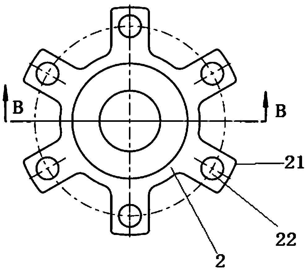
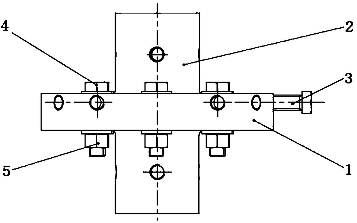
[0022] Such as figure 1 figure 2 As shown, the screw torque loader has a first flange 1 and a second flange 2, and the first flange 1 and the second flange 2 are installed coaxially.

[0023] Such as image 3 Figure 4 As shown, a recessed cavity 11 is provided at the center of the large end face of the first flange 1, and four clockwise threaded holes 14 and four counterclockwise threaded holes 15 are provided on the side wall of the recessed cavity 11, and the four clockwise threaded holes The holes 14 are evenly spaced around the center of the first flange 1 , and the four counterclockwise threaded holes 15 are also evenly spaced around the center of the first flange. Four circular arc long holes 12 are arranged on the bottom of the concave cavity 11 , and the four circular arc long holes 12 are on the same circle, and the center of each circular arc long hole 12...


PUM


Abstract

The invention relates to torque loading devices and provides a screw type torque loading device in order to solve the problem that torque loading of an existing closed parallelogram speed reducer transfer system is difficult. The screw type torque loading device comprises a first flange and a second flange. The first flange and the second flange are coaxially mounted. The screw type torque loadingdevice is characterized in that a concave cavity is formed in the end face of the big end of the first flange; a plurality of radial arms arranged around the center of the second flange at intervalsin the circumferential direction are arranged at the big end of the second flange; the radial arms are located in the concave cavity of the end face of the first flange; the sidewall of the concave cavity of the first flange is provided with a plurality of screw holes arranged at intervals in the circumferential direction; the screw holes communicate with the concave cavity of the first flange, and the axes of the screw holes are perpendicular to the axis of the first flange in a staggered mode; a torque loading bolt of which the tail end makes contact with the corresponding radial arm is arranged in each screw hole. The screw type torque loading device is simple in structure, safe and reliable, and facilitates adjustment of torque.

Description

technical field [0001] The present invention relates to a torque loader, more specifically, to a screw type torque loader. Background technique [0002] The reducer increases the torque at the output end by reducing the speed to achieve low-speed and heavy load at the output end of the reducer. For example, the rotary reducer of a certain type of excavator has a maximum torque of 745Nm at the input end and a maximum output torque of more than 18800Nm at the output end. In the design and manufacture process of the reducer, the durability of the reducer needs to be verified in order to verify the reliability and related performance of the reducer. In the common reducer operation system, two motors are generally used, one motor is used as the input, and the other motor is used as the load to realize the operation of the reducer under the maximum torque condition. The two required for such an operation system The total power of the motor needs to be large enough to meet the tes...

Claims


Application Information

Patent Timeline
IPC IPC(8): F16D1/033F16D1/12
CPCF16D1/033F16D1/12
Inventor 牛其林鄢万斌蒋仁科叶勤曹健榕
Owner GUANGXI LIUGONG MASCH CO LTD
Features
  • R&D
  • Intellectual Property
  • Life Sciences
  • Materials
  • Tech Scout
  • Unparalleled Data Quality
  • Higher Quality Content
  • 60% Fewer Hallucinations
Learn More