Round tool blank and method and device for making the same

A technology of blanks and cutting tools, applied in the field of manufacturing round cutting tools and blanks for round cutting tools, can solve problems such as powder material loss, and achieve the effect of increasing productivity and improving design

Active Publication Date: 2013-06-05
SANDVIK INTELLECTUAL PROPERTY AB
View PDF7 Cites 11 Cited by
  • Summary
  • Abstract
  • Description
  • Claims
  • Application Information

AI Technical Summary

Problems solved by technology

[0008] While providing a shape very close to the shape of the final product, the groove formation according to the above method results in a substantial loss of powder material

Method used


Image

  • Round tool blank and method and device for making the same
  • Round tool blank and method and device for making the same
  • Round tool blank and method and device for making the same

Examples


Embodiment Construction

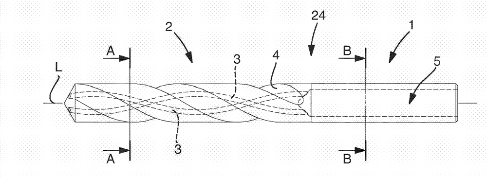
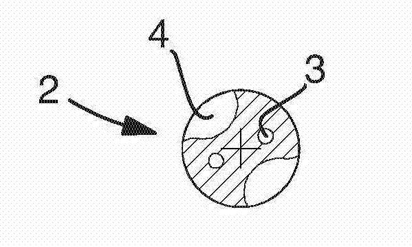
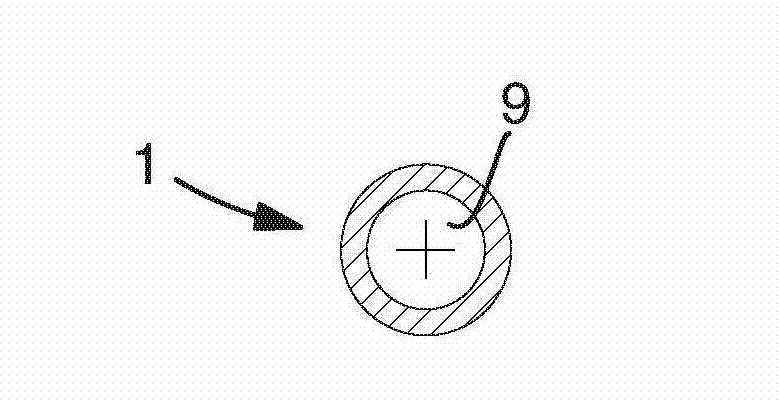
[0051] Figure 1A -D schematically discloses a drill bit 24 comprising a shank part 1 and a flute part 2 integral with the shank part 1 . The flute portion 2 refers to a portion of the drill bit 24 having chip flutes formed in its peripheral surface. This particular drill is only one example of a rounding tool according to the invention, and the invention also relates to other drill geometries as well as end mills and other rounding tools for chip forming machining by metal cutting. Hence, in the following text, the term drill bit 24 and the term rounding tool 24 can be used interchangeably. One or more internal coolant passages 3 may be provided within the drill bit 24 . For example, in Figure 1B As best shown in cross-sectional view A-A of the drill bit, the drill bit includes two internal coolant passages 3 which follow the helical chip flutes 4 of the drill bit in a torsional manner, however, the inner coolant passages 3 Arrangement, size and quantity depend on bit des...


PUM


Abstract

The present invention relates to a method and a device for manufacturing a blank for a round tool and to a blank for a round tool, and eventually to a method for manufacturing a round tool and to a round tool obtained. The device comprises a die for extrusion and a sleeve arrangement comprising a sleeve, and an end member for closing the sleeve in one end. Extrusion through the die continuously forms an extruded material comprising chip flutes and optionally internal coolant channels, which is received by the sleeve arrangement. The extruded material received by the sleeve arrangement is reworked and shaped to a shank portion after the interior shape of the sleeve arrangement. A projection of the end member protruding into the sleeve forms a bore in the blank. When the shank portion is finished the end member is released and moved forward as extrusion continues to form a fluted portion to complete the blank. The material waste is minimal in this process and since the internal coolant channels are formed simultaneously with the chip flutes in the fluted portion there is no risk of deforming the internal coolant channels. Moreover, a bore in the round tool removes unnecessary material and provides improved design of internal coolant channels.

Description

technical field [0001] The invention relates to a method and a device for producing a blank for a rounding tool and to a blank for a rounding tool and finally to a method for producing a rounding tool and to a rounding tool. Background technique [0002] A rounding tool is a term used in the field of cutting tools, and it refers to cutting tools used for chip forming machining, such as drills, end mills, thread drills, and the like. In contrast to cutting tools, rounding tools are generally elongated and manufactured as a single piece having a shank portion and a portion comprising one or more cutting edges. Typically, rounding tools include chip flutes for efficient chip removal during machining, and therefore this portion is referred to herein as a flute portion. Rounding knives are generally made of carbide or high-speed steel, but rounding knives can also be made of ceramic or cermet. [0003] The manufacture of rounding tools is usually performed in a powder metallurg...

Claims


Application Information

Patent Timeline
Patent Type & Authority Applications(China)
IPC IPC(8): B21C23/14B21C25/02B21C33/00
CPCB21C23/147E21B10/46B22F3/20B23B51/02B22F2005/004B21C37/04B22F2005/103B23B51/06B21C23/00B22F2005/001B23P15/32Y10T408/455B21C25/10B23P15/28
Inventor 埃撒卡·卡凯亨里克·埃里克森
Owner SANDVIK INTELLECTUAL PROPERTY AB
Why Eureka
Try Eureka