A controllable connection mechanism between a traction drive device and a traction component

A connection mechanism and traction drive technology, applied in the direction of transmission elements or pulley ropes or cables, mechanical equipment, belts/chains/gears, etc., can solve the problem of damage to traction components, wire ropes, cables and wire ropes, etc., to achieve Strong practicability and the effect of protecting mechanical properties

Active Publication Date: 2019-06-11
SHENZHEN FULINTECH SCI & TECH
View PDF5 Cites 0 Cited by
  • Summary
  • Abstract
  • Description
  • Claims
  • Application Information

AI Technical Summary

Problems solved by technology

[0002] At present, in the places where traction is required, such as the traction of wire ropes, cables and steel wire ropes, the traction method is to fix one end of them, and then use the traction device to move, and if the traction wire ropes, cables and steel wire ropes are longer, it will The phenomenon that the wire rope, cable and steel wire rope are damaged or tempered at the traction part directly damages the traction part, which has great limitations

Method used


Image

  • A controllable connection mechanism between a traction drive device and a traction component
  • A controllable connection mechanism between a traction drive device and a traction component
  • A controllable connection mechanism between a traction drive device and a traction component

Examples


Embodiment Construction

[0017] The following will clearly and completely describe the technical solutions in the embodiments of the present invention with reference to the accompanying drawings in the embodiments of the present invention. Obviously, the described embodiments are only some, not all, embodiments of the present invention. Based on the embodiments of the present invention, all other embodiments obtained by persons of ordinary skill in the art without making creative efforts belong to the protection scope of the present invention.

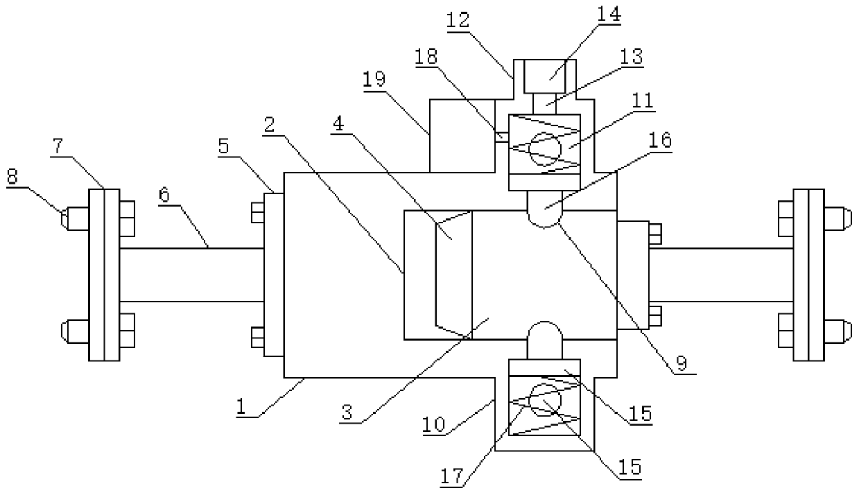
[0018] see figure 1, an embodiment provided by the present invention: comprising a cylindrical hollow sleeve 1, the center of one end surface of the cylindrical hollow sleeve 1 is provided with a main insertion groove structure 2, and the interior of the main insertion groove structure 2 is inserted into An insertion cylindrical rod 3, the insertion cylindrical rod 3 is provided with a chamfer structure 4 at one end inside the main insertion groove structure 2...


PUM


Abstract

The invention discloses a controllable connection mechanism between a traction driving device and a pulled component. The controllable connection mechanism between a traction driving device and a pulled component comprises a cylindrical hollow sleeve. A main insertion groove structure is arranged at the center of one end face of the cylindrical hollow sleeve. An insertion cylindrical rod is inserted into the main insertion groove structure. A chamfer structure is arranged at one end of the part, located in the main insertion groove structure, of the insertion cylindrical rod. A connection plate is fixed to the other end face of the insertion cylindrical rod with bolts. A connection plate is fixed to the other end face of the cylindrical hollow sleeve with bolts. The center of one end of each connection plate is connected with an air power type buffering connection mechanism. The controllable connection mechanism between the traction driving device and the pulled component can connect athread rope or a cable or a steel wire rope and the pulled component. The controllable connection mechanism between the traction driving device and the pulled component can have control over the maximum force of pull, and is controllable with control carried out with air pressure so that the mechanical property of the pulled component can be effectively protected. Furthermore, because the controllable connection mechanism between the traction driving device and the pulled component is provided with the air power type buffering connection mechanisms, the mechanical property, at the connected position, of the traction driving device can be effectively protected, and the practicability is high.

Description

technical field [0001] The invention relates to the technical field of mechanical components, in particular to a controllable connection mechanism between a traction drive device and a traction component. Background technique [0002] At present, in places where traction is required, such as the traction of wire ropes, cables and steel wire ropes, the traction method is to fix one end of them and then use the traction device to move, and if the traction wire ropes, cables and steel wire ropes are longer, it will Make wire rope, cable and steel wire rope damage or exercise phenomenon in traction part, directly damage traction part, have bigger limitation. Contents of the invention [0003] The object of the present invention is to provide a controllable connection mechanism between a traction drive device and a traction component, so as to solve the problems raised in the background art above. [0004] In order to achieve the above object, the present invention provides th...

Claims


Application Information

Patent Timeline
Patent Type & Authority Patents(China)
IPC IPC(8): F16G11/00
CPCF16G11/00
Inventor 李少许刘淑琦
Owner SHENZHEN FULINTECH SCI & TECH
Why Eureka
Try Eureka