
Medium voltage mutual inductor electronic label packaging device

A technology of electronic tags and packaging devices, which is applied in the field of transformers, can solve problems such as electricity theft, low scanning recognition rate, and errors in storage and storage systems, and achieve the effect of not being easily damaged and ensuring the appearance quality

Pending Publication Date: 2018-05-29
ZHEJIANG HORIZON INSTR TRANSFORMERS
View PDF0 Cites 4 Cited by
  • Summary
  • Abstract
  • Description
  • Claims
  • Application Information

AI Technical Summary

Problems solved by technology

[0003] However, the above method has the following problems: the two-dimensional barcode manually pasted on the transformer body is easy to fall off, easy to be damaged, the scanning recognition rate is not high, and repeated identification is easy to occur, which makes it difficult to identify the transformer; all barcodes are associated manually. Operation, when there is a mistake in manual operation, system errors will occur in the storage and out of the warehouse; when the power supply enterprise takes stock of assets, it is necessary to manually use a scanning gun to scan the barcodes one by one, resulting in high labor intensity
[0005] For medium-voltage transformers, due to their high value, if the electronic tags adopt the above method, their practicability will be affected.
If the electronic tag has a structure that is easy to disassemble, criminals will maliciously replace the electronic tag, and electricity theft will occur, which will directly cause economic losses to the power supply company.

Method used


Image

  • Medium voltage mutual inductor electronic label packaging device
  • Medium voltage mutual inductor electronic label packaging device
  • Medium voltage mutual inductor electronic label packaging device

Examples


Embodiment Construction

[0040] The following will clearly and completely describe the technical solutions in the embodiments of the present invention with reference to the accompanying drawings in the embodiments of the present invention. Obviously, the described embodiments are only some, not all, embodiments of the present invention. Based on the embodiments of the present invention, all other embodiments obtained by persons of ordinary skill in the art without making creative efforts belong to the protection scope of the present invention.

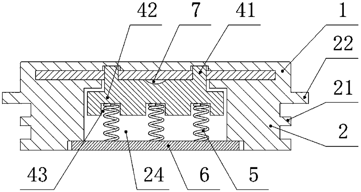
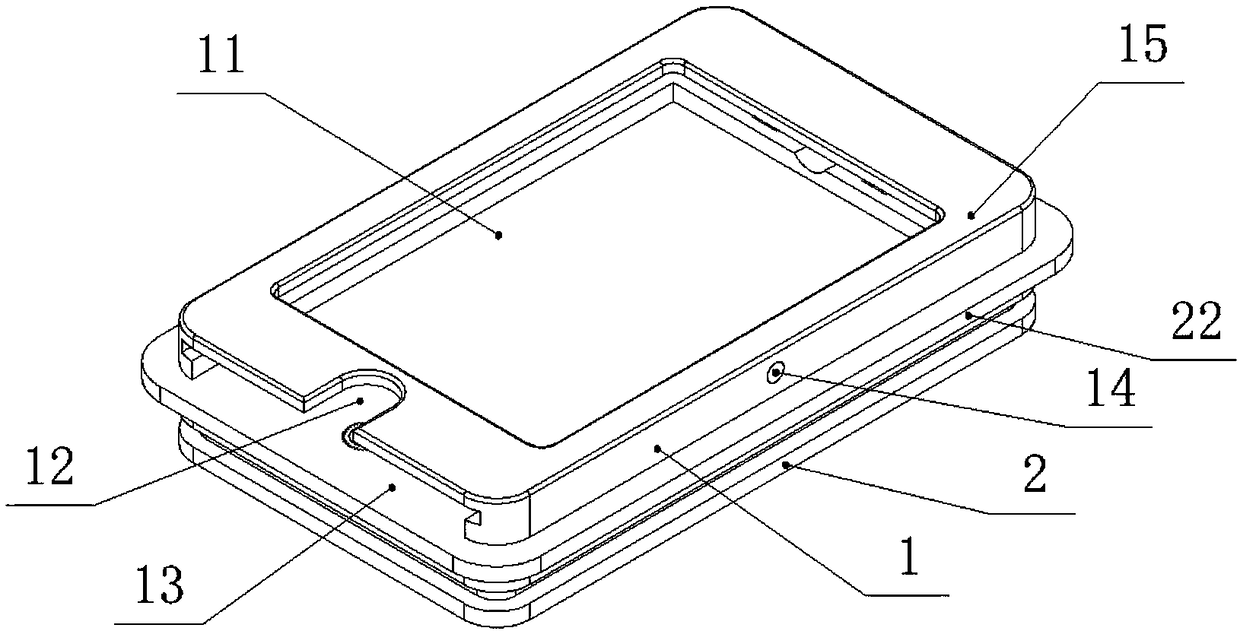
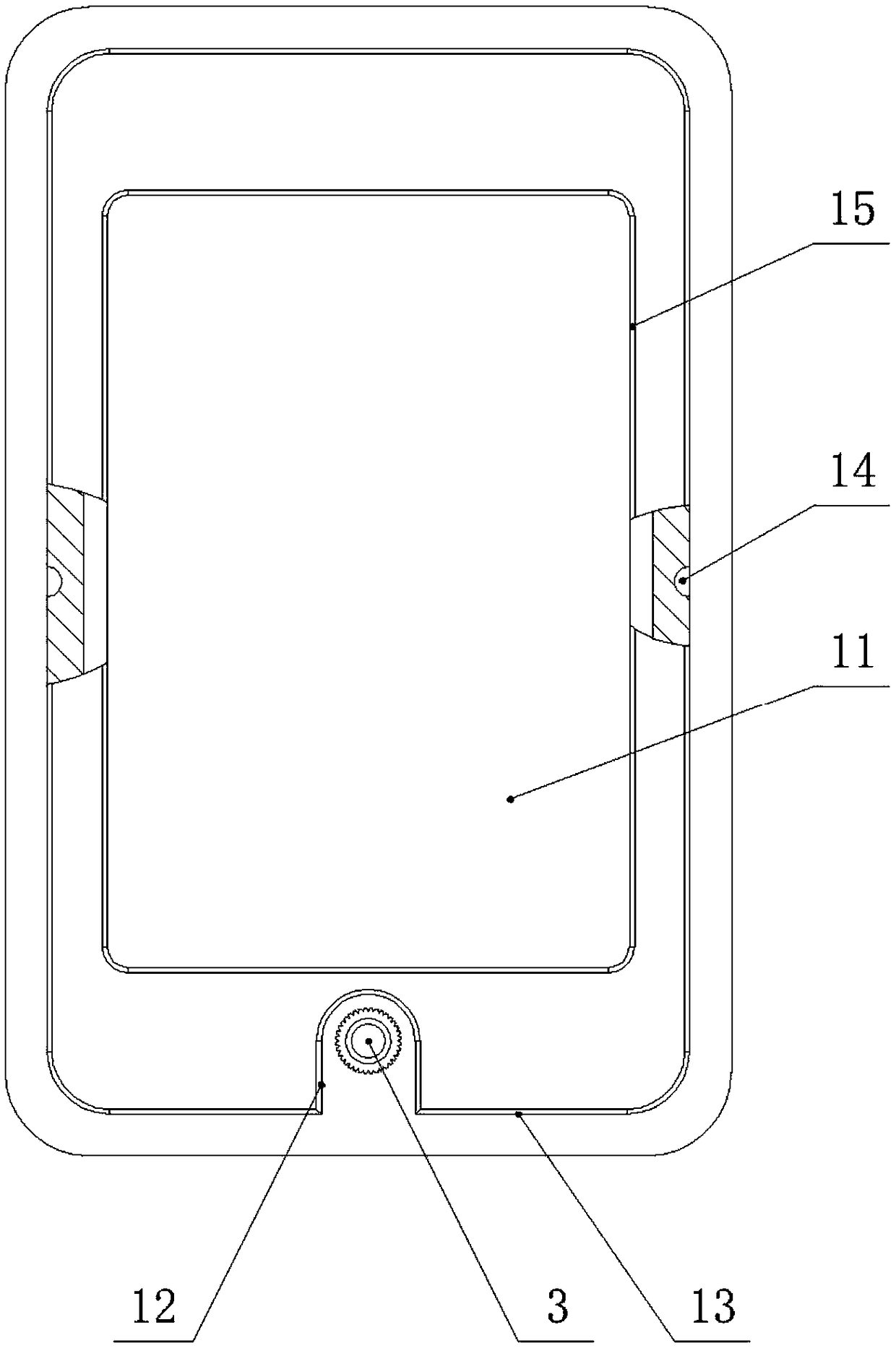
[0041] see Figure 1-14, a medium-voltage transformer electronic label packaging device, including an electronic label and an electronic label board, the electronic label board includes an upper card insertion layer 1 and a lower installation layer 2, the card insertion layer 1 and the installation layer 2 are both rectangular Structure, the card insertion layer 1 and the installation layer 2 are casted together with epoxy resin, the card insertion layer 1 is ...


PUM


Abstract

The invention discloses a medium voltage mutual inductor electronic label packaging device. An electronic label board includes an upper card insertion layer and a lower installation layer. The card insertion layer and the installation layer are integrally poured, and the card insertion layer is provided with a card insertion cavity for placing an electronic label. A card insertion port which is open is located at one side of the card insertion layer and in front of the card insertion cavity. An anti-plug umbrella skirt and a seal stop ring are arranged at the side of the installation layer. Anaccommodation cavity is arranged at the bottom of the installation layer. The accommodation cavity is communicated with the card insertion cavity. The accommodation cavity is provided with a lock assembly, a spring and a cover plate in sequence from top to bottom, the spring and the cover plate are against the lock assembly, the cover plate fixes the lock assembly and the spring in the accommodation cavity, the lock assembly comprises a lock at the top and a base at the bottom, and the top of the lock is shaped like an inclined plane. The electronic label is provided whit a locking port whichis matched with the top of the lock. The device avoids the replacement of electronic labels by lawless persons and ensures valid identity recognition of the mutual inductor during the whole life circle of the mutual inductor.

Description

technical field [0001] The invention belongs to the technical field of transformers, in particular to an electronic label packaging device for medium-voltage transformers. Background technique [0002] At present, in the process of warehousing and asset management of transformers, electric power companies generally adopt a method of manually pasting a two-dimensional barcode on the transformer body, scanning the barcode point-to-point with a scanning gun, and entering the information into the storage system. [0003] However, the above method has the following problems: the two-dimensional barcode manually pasted on the transformer body is easy to fall off, easy to be damaged, the scanning recognition rate is not high, and repeated identification is easy to occur, which makes it difficult to identify the transformer; all barcodes are associated manually. Operation, when there is a mistake in manual operation, a system error will occur in the storage and out of the warehouse;...

Claims


Application Information

Patent Timeline
Patent Type & Authority Applications(China)
IPC IPC(8): G06K19/077
CPCG06K19/07722G06K19/07724G06K19/07726G06K19/0773G06K19/07745G06K19/07749G06K19/07758G06K19/07798
Inventor 祝顺峰杨庆华吕超群唐福新叶飞
Owner ZHEJIANG HORIZON INSTR TRANSFORMERS
Learn More