
Magnetic coupling assembly and magnetic coupling stirrer mixer

一种磁性耦合、磁性件的技术,应用在具有旋转搅拌装置的混合机、电动组件、机电装置等方向,能够解决马达转速起伏变化、不尽确实、变化等问题

Active Publication Date: 2018-05-29
牟敦刚
View PDF4 Cites 4 Cited by
  • Summary
  • Abstract
  • Description
  • Claims
  • Application Information

AI Technical Summary

Problems solved by technology

[0004] 2. When rotating and stirring, especially when the stirring part rotates at a high speed, due to the inaccuracy of the above-mentioned coupling force field, positioning and strength, the stirring work without supervision for a long time may easily cause the stirring part to snake due to some external interference , wandering, jumping and coupling failure, such as the position of the stirring piece or container slipping, the fluctuation of the motor speed, the uneven bottom of the container or the change of viscosity, etc.
Different from the known device, when the instantaneous kinetic energy (momentum) or inertial force (inertia) of the sudden increase in speed is promoted, the stirring member can only return to its original position after it deviates from the original position , and can no longer walk on the magnetic component combination or find more than one alternative coupling position, and finally cannot easily slip from the above-mentioned magnetic force field, and break away from the magnetic attraction control of the driving magnetic component combination

Method used


Image

  • Magnetic coupling assembly and magnetic coupling stirrer mixer
  • Magnetic coupling assembly and magnetic coupling stirrer mixer
  • Magnetic coupling assembly and magnetic coupling stirrer mixer

Examples


Embodiment Construction

[0069] In order to make the above-mentioned purpose, features and advantages of the present invention more comprehensible, a preferred embodiment is specially given below, together with the accompanying drawings, to describe in detail as follows.

[0070] Preferred embodiments according to the present invention will be described below. It must be noted that the present invention provides many applicable inventive concepts, and the specific embodiments disclosed here are only used to illustrate specific ways to achieve and use the present invention, and are not intended to limit the scope of the present invention.

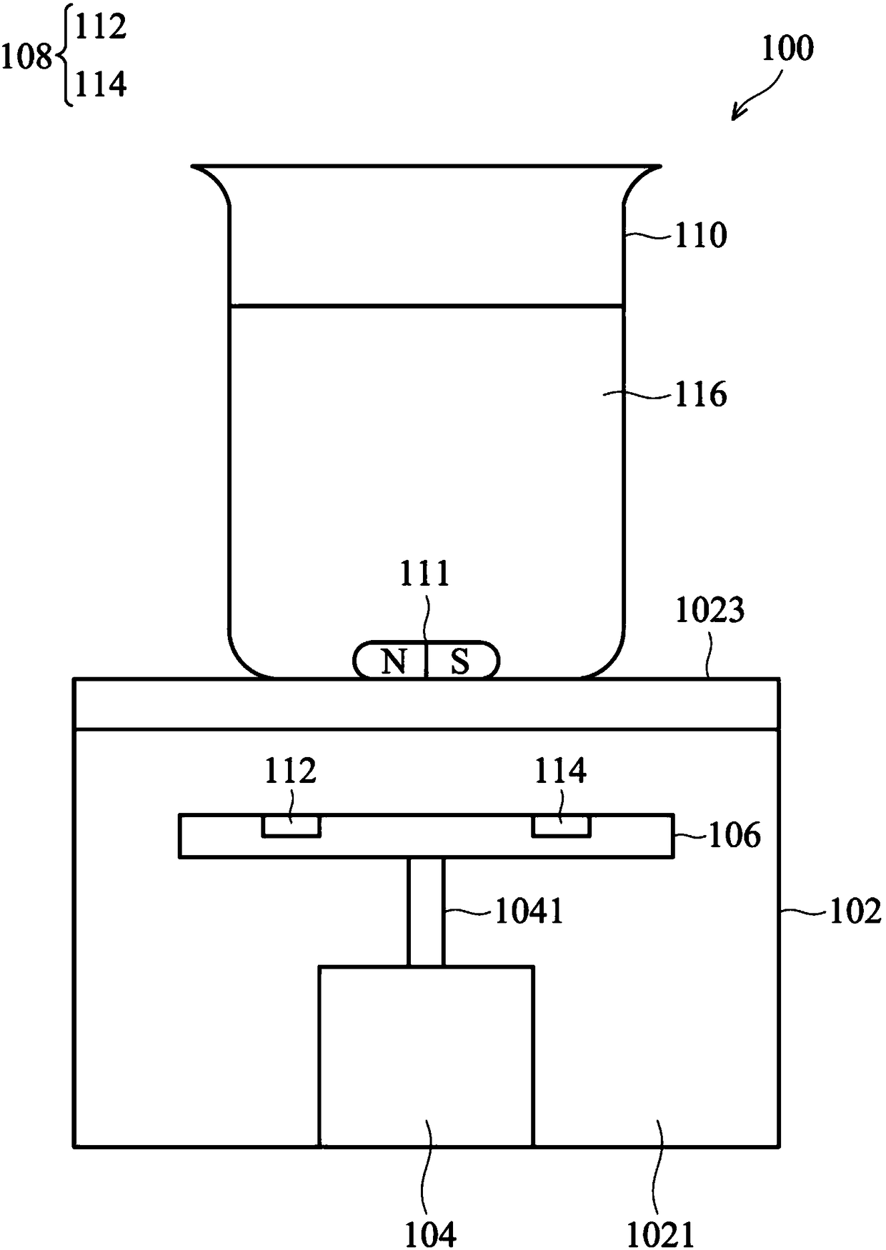
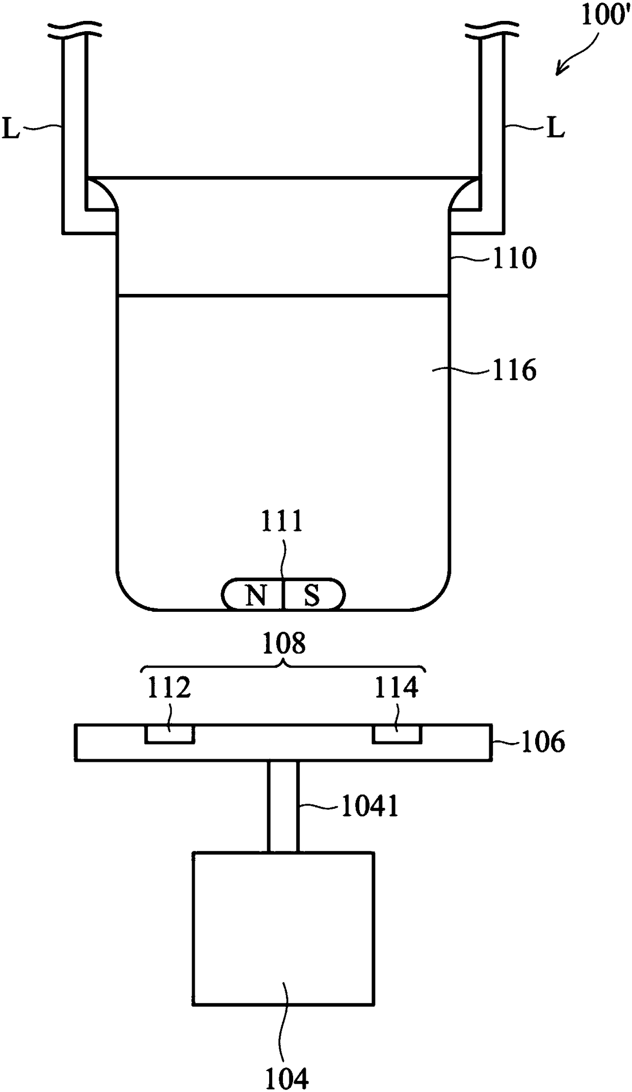
[0071] Please refer to figure 1 , figure 1 It is a schematic diagram of a magnetically coupled stirring device 100 according to an embodiment of the present invention. The magnetic coupling stirring device 100 includes a housing 102 , a motor 104 and a magnetic coupling assembly. As shown in the figure, the housing 102 has an accommodating space 1021 and a bearin...


PUM


Abstract

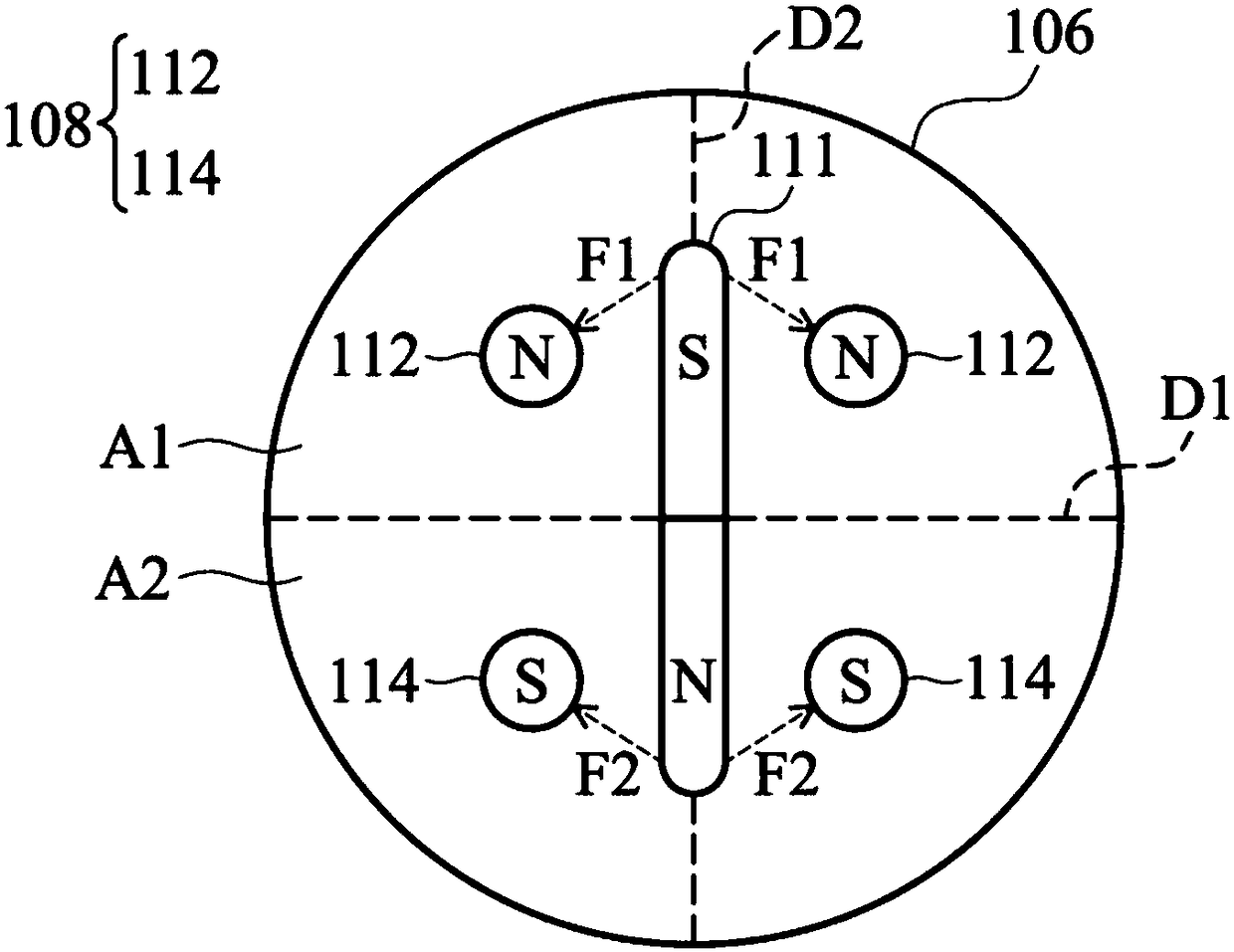
A magnetic coupling assembly and a magnetic coupling stirrer mixer are disclosed. The magnetic coupling assembly includes a rotary round disk, a magnetor assembly, a container, and a stirring member,wherein the magnetor assembly includes two north-pole (N) magnetors arranged in one side of the rotary disk and two south-pole (S) magnetors which are arranged in the other side of the rotary disk; the stirring member is axially magnetized with an N pole formed on one end and a S pole formed on the other end; the stirring member is arranged in content in the container. The two north-pole (N) magnetors are coupled to the S pole while the two south-pole (S) magnetors are coupled to the N pole. Due to the four-corner sealing structure, the stirring member is fixed at a single and unique positionwithout deflection and deformation, so that when the round disk rotates, the stirring member is fixed by the 2N=2S four corner magentic force and rotates in order to stir the content.

Description

technical field [0001] The invention relates to a coupling assembly and a coupling stirring device, in particular to a magnetic coupling assembly and a stirring device for stirring by means of magnetic coupling. Background technique [0002] Many existing chemical experiments and biological experiments are to place the liquid, solid or liquid-solid or liquid-gas content to be used in the beaker, and then use the stirring rod to stir to produce the required chemical reaction or other special purposes. However, some experiments require stirring for a long time, such as several hours or even longer, so it is impossible to stir only by manpower, so a method that can replace manpower is needed to automatically stir the liquid used in the experiment. The existing magnetic stirring device is a stirring piece coupled to the content through a magnetic device, so as to drive the stirring piece through magnetic attraction force, and then achieve the purpose of stirring the content. Ho...

Claims


Application Information

Patent Timeline
Patent Type & Authority Applications(China)
IPC IPC(8): H02K49/10B01F13/08
CPCH02K49/104H02K49/108B01F33/4531B01F33/452B01F33/4532B01F27/053B01F27/2722
Inventor 牟敦刚
Owner 牟敦刚
Learn More