Long-bone fracture reset force testing device

A technology for testing device and reset force, applied in medical science, external fixator, surgery, etc., can solve the problems of insufficient displacement and increased workload of patients, and achieve the effect of easy disinfection

Active Publication Date: 2018-06-01
SHANGHAI UNIV
View PDF7 Cites 5 Cited by
  • Summary
  • Abstract
  • Description
  • Claims
  • Application Information

AI Technical Summary

Problems solved by technology

[0002] With the increase of modern fracture accidents, the workload of doctors to perform fracture reduction on patients has increased sharply. During fracture reduction, doctors first need to measure the axial reduction force of the fracture segment, and then complete the fracture reduction with the help of a reduction robot. Currently, the reduction robot uses Most of them are basically parallel mechanisms, so it has disadvantages such as insufficient displacement when resetting the axial dislocation, and now there is no intelligent and easy-to-sterilize measuring device when measuring the axial resetting force in domestic hospitals. Many existing The device needs to be manually adjusted by the doctor. Based on this situation, the present invention designs an intelligent device that can complete the fracture reduction force test

Method used


Image

  • Long-bone fracture reset force testing device
  • Long-bone fracture reset force testing device
  • Long-bone fracture reset force testing device

Examples


Embodiment 1

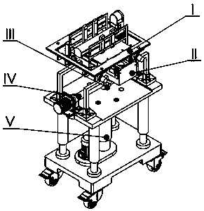
[0029] see figure 1 , The long bone fracture reduction force testing device includes a clamping mechanism (I), a lateral reduction mechanism (II), a T-shaped connection mechanism (III), a traction reduction mechanism (IV) and a lifting mechanism (V). It is characterized in that the clamping mechanism (I) is connected with the sliding block (24) in the horizontal reset mechanism (II) through the connecting plate (1), and the horizontal reset mechanism is connected with the traction reset mechanism (IV) through the T-shaped connection mechanism (III). The leading screw slide block (36) is connected, and the traction reset mechanism (IV) is installed on the lifting frame (27) in the hoisting mechanism (V) by bearing blocks (25, 35).

Embodiment 2

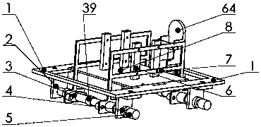
[0031] see figure 2 , this embodiment is basically the same as Embodiment 1, and the special feature is that: the clamping structure (1) includes clamping and fixing parts (6, 7) on both sides of the thigh, a leg contact bottom plate (8), a connecting plate (1 ), servo motor (5), lead screw (39) and foot fixture (64). The clamping fixtures (6, 7) on both sides of the thighs are synchronously driven by a lead screw (39) controlled by two small servo motors (5), and the clamping fixtures (6, 7) include two clamping frames (7) and four identical rectangular blocks (6), each rectangular block (6) is connected to the clamping frame (7) by 2 screws, and a patch type force sensor is attached to the rectangular block (6); two The screw (39) rotates through the 4 L-shaped connecting plates (2) below the connecting plate (1), and two screw sliders (3) are screwed on each screw (39) installed in parallel. The two ends of the lower side of the holder (7) are respectively fixed on the two...

Embodiment 3

[0033] see image 3 , this embodiment is basically the same as Embodiment 1, and the special feature is that: the foot fixing part (64) includes an h-shaped connecting part (11), a screw (17), a foot connecting part (9, 10), 6 a fixing nut, the foot connecting piece (9, 10) includes a foot connecting plate (9) and a foot fixing ring (10), and one end of the foot fixing ring (10) is hinged to the foot connecting plate (9) One side is connected, and the other end of the foot fixing ring (10) is fixed to the other side of the foot connecting plate (9) by screws. The screw (17) is placed in a long groove at the front end of the connecting plate (1), and the screw ( 17) Fix on both sides of the long slot with large nuts (13, 14), and two h-shaped connectors (11) are fixed at both ends of the screw (17) with small nuts (12, 15, 16, 18), h-shaped connection The part (11) is connected with the foot connecting plate (9) through screws, and the said foot fixing part can adjust the scre...


PUM


Abstract

The invention discloses a long-bone fracture reset force testing device, and belongs to the technical field of medical instruments. The reset force testing device comprises a clamping mechanism, a horizontal reset mechanism, a T-shaped connecting mechanism, a traction reset mechanism and a lifting mechanism, the clamping mechanism is fixed above the horizontal reset mechanism through a connectingplate, the horizontal reset mechanism is connected with the traction reset mechanism through the T-shaped connecting mechanism, and the traction reset mechanism is mounted above the lifting mechanism.According to the reset force testing device, horizontal reset, longitudinal traction and vertical lifting motion can be achieved, and the reset force testing device has the advantages that the deviceis detachable, easy to disinfect, simple in structure, intelligent and the like.

Description

technical field [0001] The invention relates to a long bone fracture reduction force testing device, which is composed of a clamping mechanism, a lateral reset mechanism, a T-shaped connection mechanism, a traction reset mechanism and a lifting mechanism. Through the coordinated movement of the clamping mechanism, the lateral reset mechanism, the traction reset mechanism and the lifting mechanism, the traction, lateral and up-and-down movement of the distal end of the long bone fracture can be well realized. It has a simple and compact design structure, detachable contact parts, and intelligent mechanism movement. The invention is suitable for preoperative reduction force testing of fracture patients and partial fracture reduction, and can improve the measurement accuracy of reduction force and improve the work efficiency of doctors. Background technique [0002] With the increase of modern fracture accidents, the workload of doctors to perform fracture reduction on patients...

Claims


Application Information

Patent Timeline
IPC IPC(8): A61B17/66A61B90/00
CPCA61B17/66A61B90/06A61B2090/064
Inventor 雷静桃王洋张恒程利亚陈子衡秦湘政
Owner SHANGHAI UNIV
Why Eureka
Try Eureka