
Parallel separation chamber of super-conducting magnetic separator and method of achieving uniform water distribution therewith

A sorting cavity and superconducting magnetic technology, applied in the direction of high gradient magnetic separator, etc., can solve the problem of uneven water distribution, achieve the effect of improving the precision of ore dressing, avoiding clogging, improving the processing precision and the stability of industrial production

Inactive Publication Date: 2018-06-01
江苏旌凯中科超导高技术有限公司
View PDF0 Cites 1 Cited by
  • Summary
  • Abstract
  • Description
  • Claims
  • Application Information

AI Technical Summary

Problems solved by technology

[0008] In view of the problem of uneven water distribution in the traditional parallel series tank system, the purpose of the present invention is to provide an improved superconducting magnetic separator parallel separation chamber and a method for realizing uniform water distribution, which can greatly reduce the supply of ore and chemicals. Inhomogeneity of water distribution in parallel tanks connected in series during cleaning and off-site flushing to improve beneficiation accuracy and avoid clogging

Method used


Image

  • Parallel separation chamber of super-conducting magnetic separator and method of achieving uniform water distribution therewith
  • Parallel separation chamber of super-conducting magnetic separator and method of achieving uniform water distribution therewith
  • Parallel separation chamber of super-conducting magnetic separator and method of achieving uniform water distribution therewith

Examples


Embodiment 1

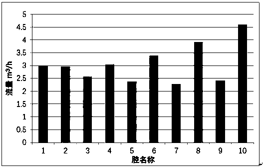
[0034] 500mm caliber, effective magnetic field length 1200mm Superconducting magnetic separator, divided into 10 sorting chambers, each sorting chamber has an effective steel wool area length of 100mm; the inner diameter of the water inlet pipe is 150mm, and the cross-sectional area is 17662.5mm 2 , the interval of the return water channel outside the outer sleeve is 30mm, and the converted cross-sectional area is about 20000mm 2 . If the flow field is not optimized, the pressure distribution of the ore feed flow field of the 10 cavities is as follows figure 1 As shown, the ore flow estimation of 10 cavities is as follows figure 2 shown. Utilize the technical solution provided by this patent to greatly reduce the cross-sectional area of ​​the water channel of the outer sleeve to less than 3000mm 2 , the total cross-sectional area of ​​water distribution of 5 groups of outer sleeve water channels is less than 15000mm 2 , at this time the flow estimates of the 10 cavities a...

Embodiment 2

[0036] 500mm caliber, effective magnetic field length 1200mm Superconducting magnetic separator, divided into 10 sorting chambers, each sorting chamber has an effective steel wool area length of 100mm; the inner diameter of the water inlet pipe is 150mm, and the cross-sectional area is 17662.5mm 2 , the interval of the return water channel outside the outer sleeve is 30mm, and the converted cross-sectional area is about 20000mm 2 . If the flow field is not optimized, the pressure distribution of the ore feed flow field of the 10 cavities is as follows figure 1 As shown, the ore flow estimation of 10 cavities is as follows figure 2 shown. Using the technical solution provided by this patent, a baffle is added to the steel wool cross-section of the 10 cavities, and small holes with a diameter of 5mm are drilled on the baffle, and the total water cross-sectional area of ​​all the small water holes is 1500mm 2 , the total cross-sectional area of ​​10 parallel cavity baffles is...


PUM


Abstract

The invention discloses a parallel separation chamber of super-conducting magnetic separator and a method of achieving uniform water distribution therewith. The separation chamber comprises a water inlet pipe, an outer sleeve, and a separation chamber located therebetween. A plurality of separation zones, of which the quantity is an even number, are uniformly distributed in the separation chamberin parallel, a high-gradient medium arranged in each separation zone; a water inlet pipe water channel is annularly arranged on the water inlet pipe at the corresponding position between each two separation zones; an outer sleeve water channel is arranged on the outer sleeve in an annular manner; one or more of the total area of the water distribution cross section of the water inlet pipe water channel, the total area of the water passing cross section of the high-gradient medium, and the total area of the water distribution cross section of the outer sleeve, which are corresponding to the separation zones, are smaller than the area of the cross section of the water inlet pipe or the area of the cross section of an outer water backflow channel of the outer sleeve, which is subjected to thesmaller number. The parallel separation chamber allows uniform water distribution, so that process precision and industrial production stability of the super-conducting magnetic separator system aregreatly improved, and continuous industrial production of the super-conducting magnetic separator is ensured.

Description

technical field [0001] The invention relates to an ore pulp magnetic separation equipment, in particular to a parallel separation chamber of a superconducting magnetic separator and a method for realizing uniform water distribution. Background technique [0002] The solenoid superconducting magnetic separator generally adopts the reciprocating series tank sorting structure. The magnet is placed horizontally. The axis of the magnet is parallel to the horizontal plane. The reciprocating series tank passes through the magnet and is divided into two working areas and three dummy units. (Magnetic balance area) One working area operates in the magnetic field while the other working area elutes outside the magnetic field. This structure was patented by the United Kingdom many years ago and has expired. Outotec and other foreign superconducting magnetic separator manufacturers and domestic equipment companies such as Jiangsu Jingkai and Shandong Huate all adopt this sorting structur...

Claims


Application Information

Patent Timeline
Patent Type & Authority Applications(China)
IPC IPC(8): B03C1/025B03C1/032B03C1/031
CPCB03C1/025B03C1/031B03C1/032
Inventor 马仲英袁君辉
Owner 江苏旌凯中科超导高技术有限公司
Learn More