Positioning and clamping mechanism and laser processing system
A positioning clamping and clamping head technology, applied in laser welding equipment, metal processing equipment, manufacturing tools, etc., can solve the problems of glass clamping damage, increased scrap rate, etc., and achieves fast speed, convenient installation and use, and structural Simple and reasonable effect
- Summary
- Abstract
- Description
- Claims
- Application Information
AI Technical Summary
Problems solved by technology
Method used
Image

Examples
Embodiment
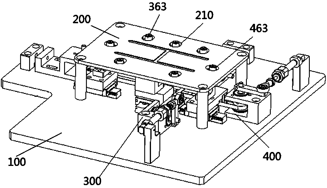
[0039] seefigure 1 - Figure 4 , this embodiment provides a positioning and clamping mechanism, which is used to install on the laser processing equipment to perform positioning and clamping on the workpiece, so as to ensure safe and reliable processing of the workpiece.
[0040] The positioning and clamping mechanism provided in this embodiment includes a base 100 , a carrier 200 , a first clamping assembly 300 and a second clamping assembly 400 . The first clamping assembly 300 and the second clamping assembly 400 are installed on the base 100 , and the first clamping assembly 300 and the second clamping assembly 400 jointly realize the clamping of the workpiece.
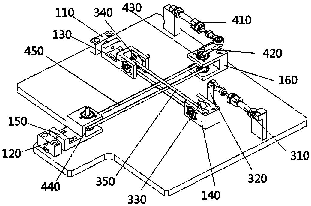
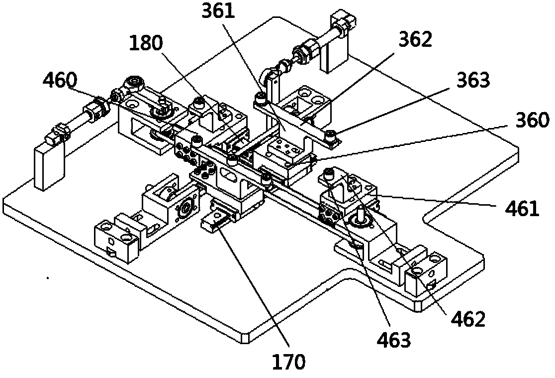
[0041] In this embodiment, optionally, the base 100 is provided with a first fixing base 110, a second fixing base 120, a pair of first mounting base 130 and a second mounting base 140, and a pair of third mounting bases. seat 150 and the fourth mounting seat 160, the first mounting seat 130 is slidably arranged ...
PUM
 Abstract
Description
Claims
Application Information
 - R&D
- Intellectual Property
- Life Sciences
- Materials
- Tech Scout
- Unparalleled Data Quality
- Higher Quality Content
- 60% Fewer Hallucinations
Browse by: Latest US Patents, China's latest patents, Technical Efficacy Thesaurus, Application Domain, Technology Topic, Popular Technical Reports.
© 2025 PatSnap. All rights reserved.Legal|Privacy policy|Modern Slavery Act Transparency Statement|Sitemap|About US| Contact US: help@patsnap.com