
A Kiss Cut Waverider Design Method with a Given 3D Front Line

A design method and waverider technology, applied in computer-aided design, calculation, instrument, etc., can solve the problem that the three-dimensional leading edge line cannot be directly specified

Active Publication Date: 2018-10-26
NAT UNIV OF DEFENSE TECH
View PDF6 Cites 0 Cited by
  • Summary
  • Abstract
  • Description
  • Claims
  • Application Information

AI Technical Summary

Problems solved by technology

[0004] The purpose of the present invention is to provide a kiss-cut waverider design method with a given three-dimensional leading edge line to solve the problem that the existing design method cannot directly specify the three-dimensional leading edge line

Method used


Image

  • A Kiss Cut Waverider Design Method with a Given 3D Front Line
  • A Kiss Cut Waverider Design Method with a Given 3D Front Line
  • A Kiss Cut Waverider Design Method with a Given 3D Front Line

Examples


Embodiment Construction

[0049] The present invention will be further described in detail below in conjunction with specific embodiments and accompanying drawings.

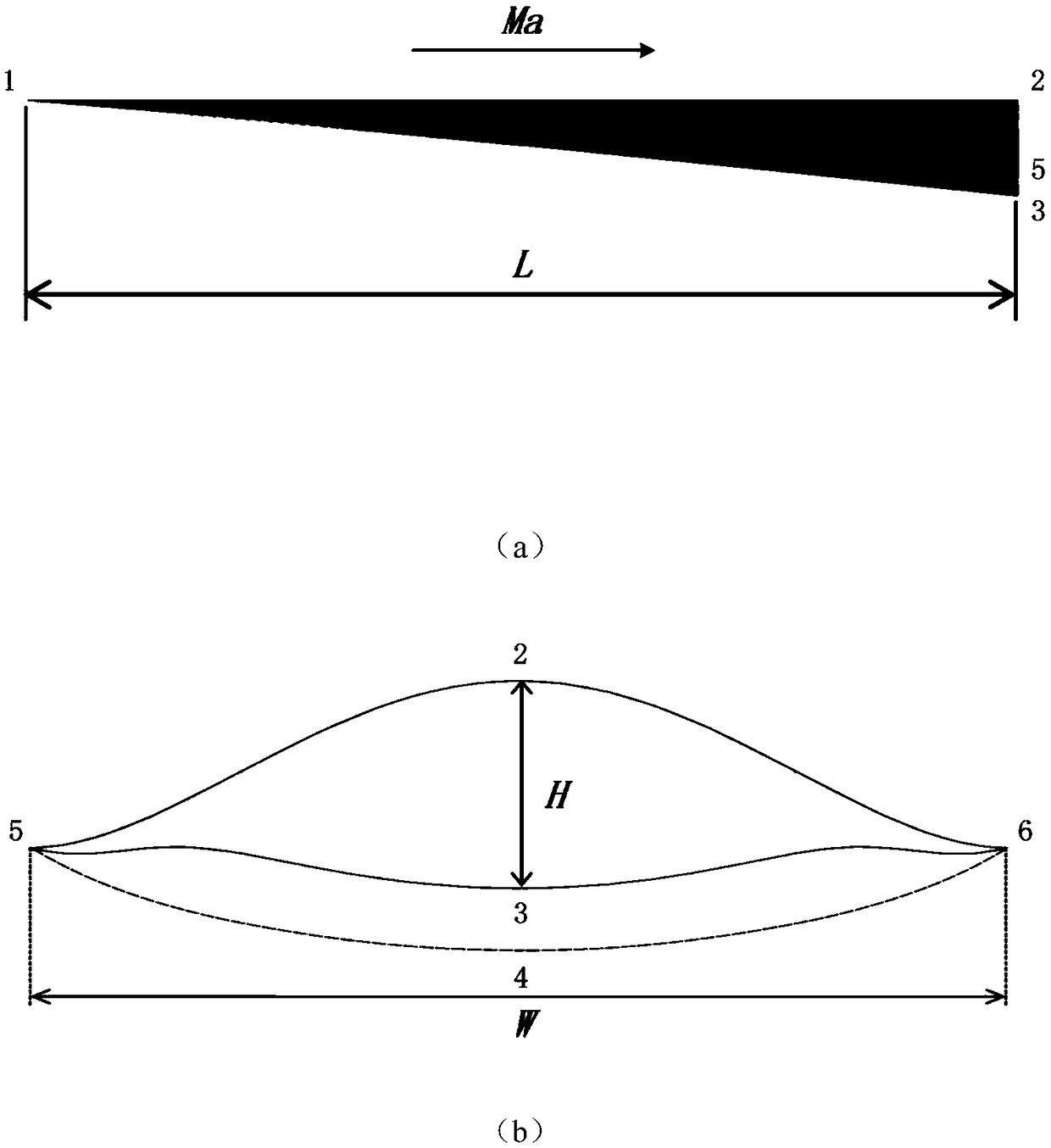
[0050] Firstly, the typical lines and surfaces of the waveriders to be designed are introduced, refer to figure 1 is a schematic diagram of the geometric parameters of the waverider part, figure 1 where Ma is the Mach number of the incoming flow, L is the length of the waverider, H is the height of the waverider, W is the wingspan of the waverider, points 1, 2, 3, and 4 are the three-dimensional leading edge line and upper edge of the waverider, respectively. The midpoint of the surface exit profile, the bottom surface exit profile, and the shock wave exit profile, and points 5 and 6 are the three-dimensional leading edge line, top surface exit profile, bottom surface exit profile, and shock wave exit of the waverider The two intersection points where these four typical molded lines intersect, curve 5-1-6 is the three-dimensional leading...


PUM


Abstract

The invention provides a three-dimensional front edge line given osculating waverider design method and solves the problem of failure in direct designation of three-dimensional front edge lines in anexisting design method. By giving of a three-dimensional front edge line and flow field parameters, a corresponding shock wave outlet profile line is calculated according to the three-dimensional front edge line to complete osculating plane flow field calculation to finally generate a corresponding waverider. On the basis of an osculating cone principle, the waverider is designed under the condition that only the three-dimensional front edge line and flow field parameters are given, consideration of influences of shock wave profile lines is avoided, the three-dimensional front edge line is controlled directly, and as-required design of the waverider with requirements on the three-dimensional front edge line in engineering is realized.

Description

technical field [0001] The invention belongs to the technical field of hypersonic vehicles, in particular to a design method for a kiss-cut waverider with a given three-dimensional leading edge line. Background technique [0002] The waverider design is one of the key points and hotspots in the current research on the aerodynamic layout of hypersonic vehicles in the world. The current design methods are mainly divided into two categories: one is the design theory of a given shock generator, and the other is the kissing design theory (including kissing cone and kissing axisymmetric). The former is to obtain the lower compression surface of the waverider by tracing the streamline along a given leading edge profile in the reference flow field, which can be axisymmetric or non-axisymmetric. See Li Yongzhou, Sun Di, Zhang Kunyuan. Design of waveriders with simultaneous controllable front and rear edge profiles [J]. Acta Aeronautica Sinica, 2017,38(1):120153. [0003] Based on t...

Claims


Application Information

Patent Timeline
Patent Type & Authority Patents(China)
IPC IPC(8): B64F5/00G06F17/50
CPCB64F5/00G06F30/15G06F2113/28
Inventor 王晓燕柳军符翔陈韶华丁峰吴世超
Owner NAT UNIV OF DEFENSE TECH
Learn More