Improved type bridge equipment

An improved, bridge technology, applied in the direction of roads, road repair, roads, etc., can solve the problems of cumbersome operation, unchanged, slow down the construction progress, etc., and achieve the effect of simple device structure

Inactive Publication Date: 2018-06-01
泉州旗信专利技术咨询有限公司
View PDF4 Cites 0 Cited by
  • Summary
  • Abstract
  • Description
  • Claims
  • Application Information

AI Technical Summary

Problems solved by technology

[0002] In the daily maintenance of bridges, the filling of the potholes on the bridge road surface is an important maintenance item. In the filling work, the concrete required for filling is usually put into the container for easy retrieval. However, the traditional technology is used to store Concrete containers are generally large in size, and the material is not changed by manpower, which seriously slows down the construction progress and the equipment used for material retrieval is easy to cause damage to the container. There are also many maintenance systems that can automatically feed materials. equipment, but its use cost is high, the operation is cumbersome, and the feeding chute is fixed outside and is easily damaged by external factors, which has great disadvantages and needs to be improved

Method used


Image

  • Improved type bridge equipment
  • Improved type bridge equipment
  • Improved type bridge equipment

Examples


Embodiment Construction

[0022] All features disclosed in this specification, or steps in all methods or processes disclosed, may be combined in any manner, except for mutually exclusive features and / or steps.

[0023] Any feature disclosed in this specification (including any appended claims, abstract and drawings), unless expressly stated otherwise, may be replaced by alternative features which are equivalent or serve a similar purpose. That is, unless expressly stated otherwise, each feature is one example only of a series of equivalent or similar features.

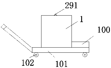
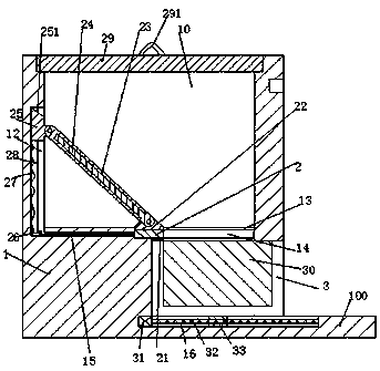
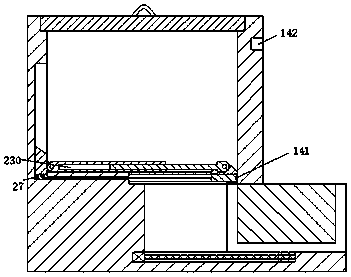
[0024] Such as Figure 1-3 As shown, a kind of improved bridge equipment of the present invention comprises container 1, and the bottom of described container 1 is fixed with trolley 101, and four corners of the bottom of described trolley 101 are provided with roller 102 at the same time, through The trolley 101 can make the container 1 easier to move, and the container 1 is provided with a cavity 10 with the notch facing upwards and a movin...


PUM


Abstract

The invention provides a piece of improved type bridge equipment. The equipment comprises a containing box, the bottom part of the containing box is fixedly provided with a trolley, four corners of the bottom part of the trolley are provided with rollers at the same time, and the containing box is provided with a containing chamber with an upward notch and a pushing groove with a notch toward to the right below the containing chamber; a cover body is installed at the upper end of the containing chamber, a discharging port is arranged between the containing chamber and the pushing groove, a pushing member is slidely installed in the pushing groove, and the pushing member is provided with a containing groove with an upward notch; a straight plate which extends to the right is arranged at theright end of the bottom wall of the pushing groove, a first sliding groove with an upward groove is arranged at the bottom wall of the sliding groove and in the straight plate, the first sliding groove is slidely provided with a first sliding block, and a spiral rod is matched and installed in the first sliding block with spiral lines; the right end of the spiral rod is rotarily installed in theright end wall of the first sliding groove, the left end is connected to a motor which is fixedly installed in the left end wall of the first sliding groove, the front and back end wall of an outlet is provided with a guiding groove which extends from left to right, and the guiding groove is slidely provided with a sliding plate which extends back and forth.

Description

technical field [0001] The invention relates to the technical field of bridge facilities, in particular to an improved bridge facility. Background technique [0002] In the daily maintenance of bridges, the filling of the potholes on the bridge road surface is an important maintenance item. In the filling work, the concrete required for filling is usually put into the container for easy retrieval. However, the traditional technology is used to store Concrete containers are generally large in size, and the material is not changed by manpower, which seriously slows down the construction progress and the equipment used for material retrieval is easy to cause damage to the container. There are also many maintenance systems that can automatically feed materials. equipment, but its use cost is high, the operation is cumbersome, and the feeding chute is fixed outside and easily damaged by external factors, which has great disadvantages and needs to be improved. Contents of the in...

Claims


Application Information

Patent Timeline
IPC IPC(8): E01C23/09
CPCE01C23/0973
Inventor 黄桂珠阮哲栋
Owner 泉州旗信专利技术咨询有限公司
Why Eureka
Try Eureka