
Prefabricated self-restoring concrete filled steel tube composite joint, installation method and structural system

A technology of steel pipe concrete and combined joints, which is applied in the direction of building construction and construction, can solve problems that need to be researched and developed, and achieve the effect of saving economic costs and time costs and increasing joint stiffness

Active Publication Date: 2019-02-05
QINGDAO TECHNOLOGICAL UNIVERSITY
View PDF22 Cites 0 Cited by
  • Summary
  • Abstract
  • Description
  • Claims
  • Application Information

AI Technical Summary

Problems solved by technology

However, the self-restoration between columns using high-strength steel reinforced concrete-filled steel tube composite joints needs to be researched and developed.

Method used


Image

  • Prefabricated self-restoring concrete filled steel tube composite joint, installation method and structural system
  • Prefabricated self-restoring concrete filled steel tube composite joint, installation method and structural system
  • Prefabricated self-restoring concrete filled steel tube composite joint, installation method and structural system

Examples


Embodiment 1

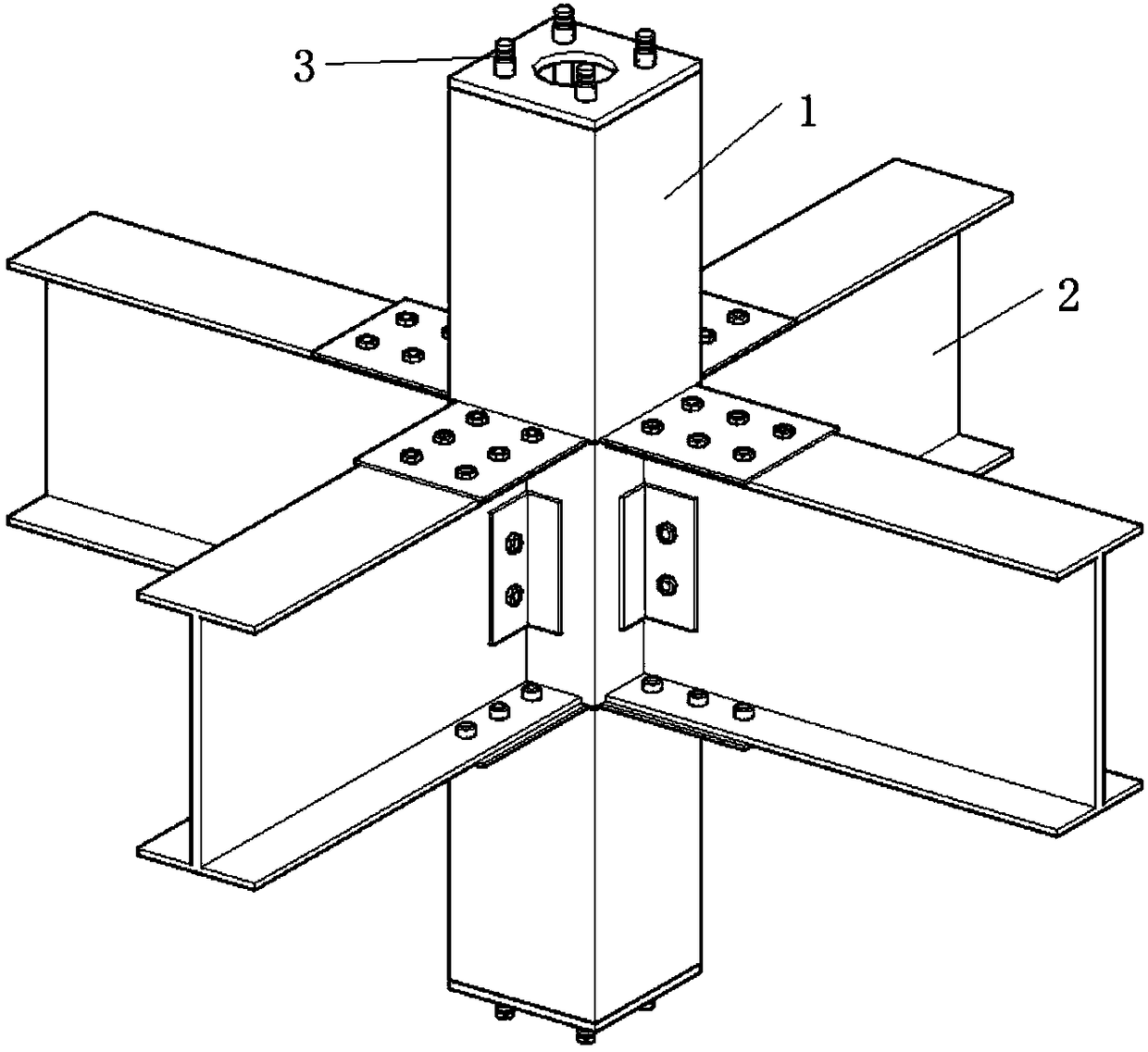
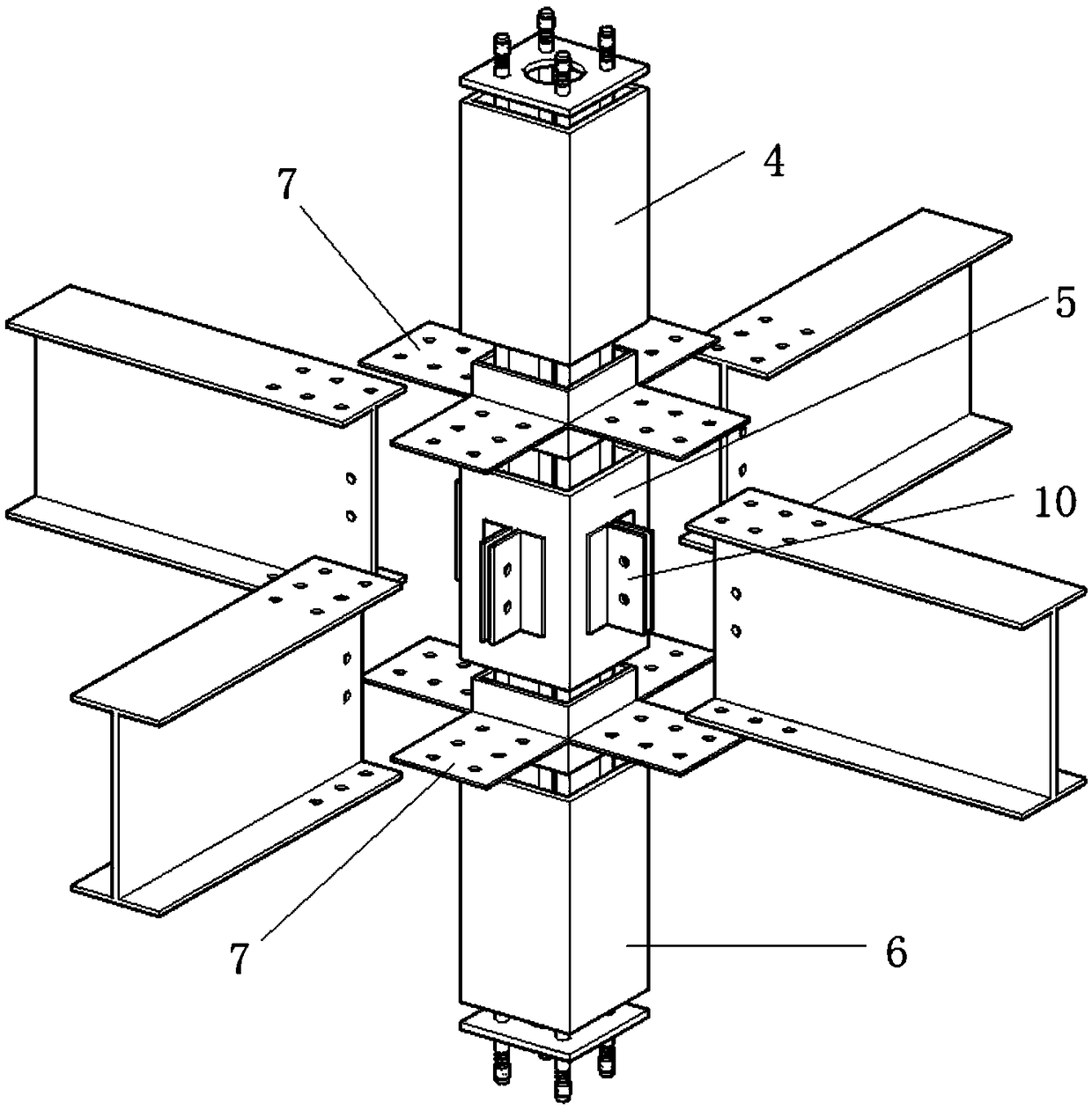
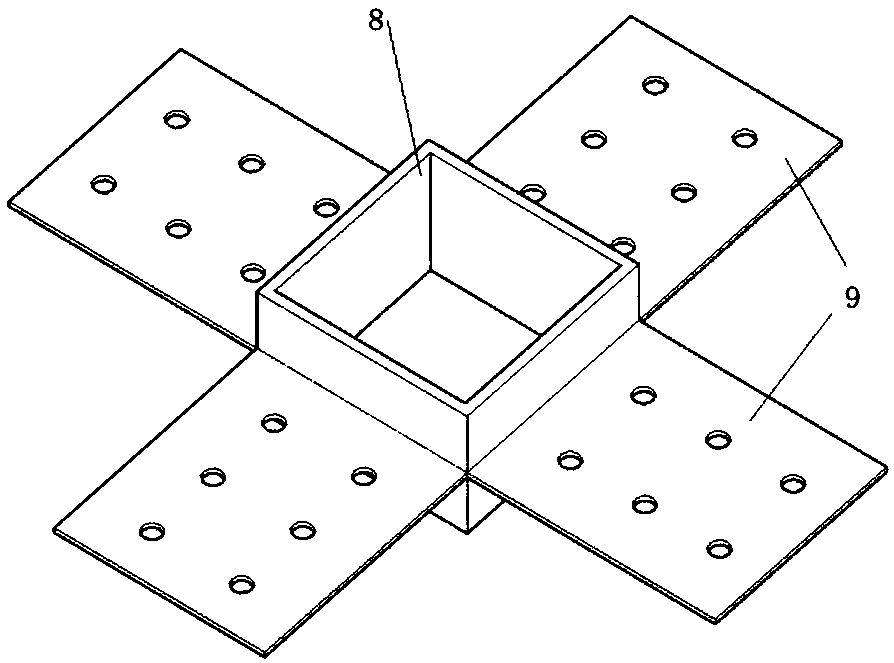
[0050] Such as figure 1 with figure 2 As shown, the assembled self-recovering steel pipe concrete composite node of the present invention includes a square steel pipe column I1 and four H-shaped steel beams 2, the steel bar 3 runs through the square steel pipe column I, and the square steel pipe column I includes the upper steel pipe column 4, The central steel pipe column 5 and the lower steel pipe column 6, the upper steel pipe column and the central steel pipe column, and the central steel pipe column and the lower steel pipe column are all connected by sleeve connectors 7;

[0051] The upper end of the upper steel pipe column and the lower end of the lower steel pipe column are all welded with a steel bar fixing plate 12, and the center of the steel bar fixing plate is provided with a through hole 11 for pouring concrete. The steel bars pass through the steel bar fixing plate at the upper end of the steel pipe column in the upper section, the square steel pipe column I a...

Embodiment 2

[0066] Such as Figure 11 , 12 As shown, the difference between this embodiment and Embodiment 1 is that the steel pipe column at the beam-column node in the middle adopts a sleeve-type steel pipe column, and the sleeve-type steel pipe column includes a square steel pipe column II17 and a round steel pipe column 18, and the round steel pipe column Set inside the square steel pipe column II; the upper and lower layers of sleeve-type steel pipe columns are connected by double-sleeve connectors, which include square outer sleeves 19 and circular inner sleeves 20, and square outer sleeves. The sleeve is arranged outside the square steel pipe column II, the circular inner sleeve is arranged inside the round steel pipe column, the lower end of the upper square steel pipe column II, the upper end of the lower square steel pipe column II, the lower end of the upper round steel pipe column and the upper end of the lower round steel pipe column Bolt holes, the square outer sleeve and t...


PUM


Abstract

The invention relates to the technical field of structural component of construction, and discloses a fabricated self-recovery concrete filled steel tube composite joint and a structural system. The joint comprises a square steel column and an H-shaped steel beam; reinforcing steel bars penetrate through the interior of the square steel column; the square steel column comprises an upper section steel pipe column, a center steel pipe column and a lower section steel pipe column; the connection between the upper section steel pipe column and the center steel pipe column and the connection between the center steel pipe column and the lower section steel pipe column are through sleeve connecting pieces; a steel beam connecting piece is fixed on the side edge of the center steel pipe column; and the H-shaped steel beam is connected with the steel pipe column through the steel beam connecting piece and the sleeve connecting pieces. The joint force of the fabricated self-recovery concrete filled steel tube composite joint is reasonable and clear, the scheme is simple, the construction is convenient, the self-recovery vibration control effect can be well realized, the safety of a structureunder an earthquake action is ensured, and the fabricated self-recovery concrete filled steel tube composite joint and the structural system can be widely used in the technical field of energy dissipation and damping of the building structure.

Description

technical field [0001] The invention relates to the technical field of building structural components, in particular to an assembled self-restoring steel pipe concrete composite node, an installation method and a structural system. Background technique [0002] Steel structure buildings have the characteristics of high strength, light weight, fast construction speed, good seismic performance and high degree of industrialization. Steel structural components form a structural system by connecting nodes, and the choice of node form has a direct impact on structural integrity, reliability, construction period, and the design and construction of auxiliary components. [0003] Recoverable functional structure is a new type of shock-absorbing control structure. It can not only protect people's lives and property during earthquakes, but also help people return to normal life as soon as possible after a major earthquake. It is an ideal new structure for seismic design. direction. R...

Claims


Application Information

Patent Timeline
Patent Type & Authority Patents(China)
IPC IPC(8): E04B1/30E04B1/58
CPCE04B1/30E04B1/5812
Inventor 牟犇王君昌刘贞涛李洋杨婷婷何宝杰
Owner QINGDAO TECHNOLOGICAL UNIVERSITY
Learn More