Novel high-pressure water sealing pump

A high-pressure, water pump technology, used in pumps, pump components, non-variable-capacity pumps, etc., can solve the problems of low pump service life, affecting pump displacement, easy bearing damage, etc., to reduce maintenance costs, improve service life, Wear reduction effect

Pending Publication Date: 2018-06-01
宁波瑞德森船用泵制造有限公司
View PDF0 Cites 1 Cited by
  • Summary
  • Abstract
  • Description
  • Claims
  • Application Information

AI Technical Summary

Problems solved by technology

In addition, due to the small flow rate and high pressure of the sealed water pump, when the pump head is high, the single-stage pump cannot meet the requirements, and multiple impellers need to be designed to meet the requirements. The impellers need to be installed in series, resulting in large axial force and easy damage to the bearings. Resulting in low pump life
Moreover, a sealing member is provided between the partition wall and the main shaft sleeve in the existing sealed water pump structure, and the sealing member adopts a metal ring sealing structure. gap, and because there is a certain pressure difference between the chambers, the setting of the gap is bound to cause leakage. When the pump is first shipped from the factory, the gap value is within a reasonable range. When the liquid is liquid, the gap value will become larger and larger, and when the gap value reaches a certain level, it will affect the displacement of the pump.

Method used


Image

  • Novel high-pressure water sealing pump
  • Novel high-pressure water sealing pump
  • Novel high-pressure water sealing pump

Examples


Embodiment Construction

[0016] The following description serves to disclose the present invention to enable those skilled in the art to carry out the present invention. The preferred embodiments described below are only examples, and those skilled in the art can devise other obvious variations.

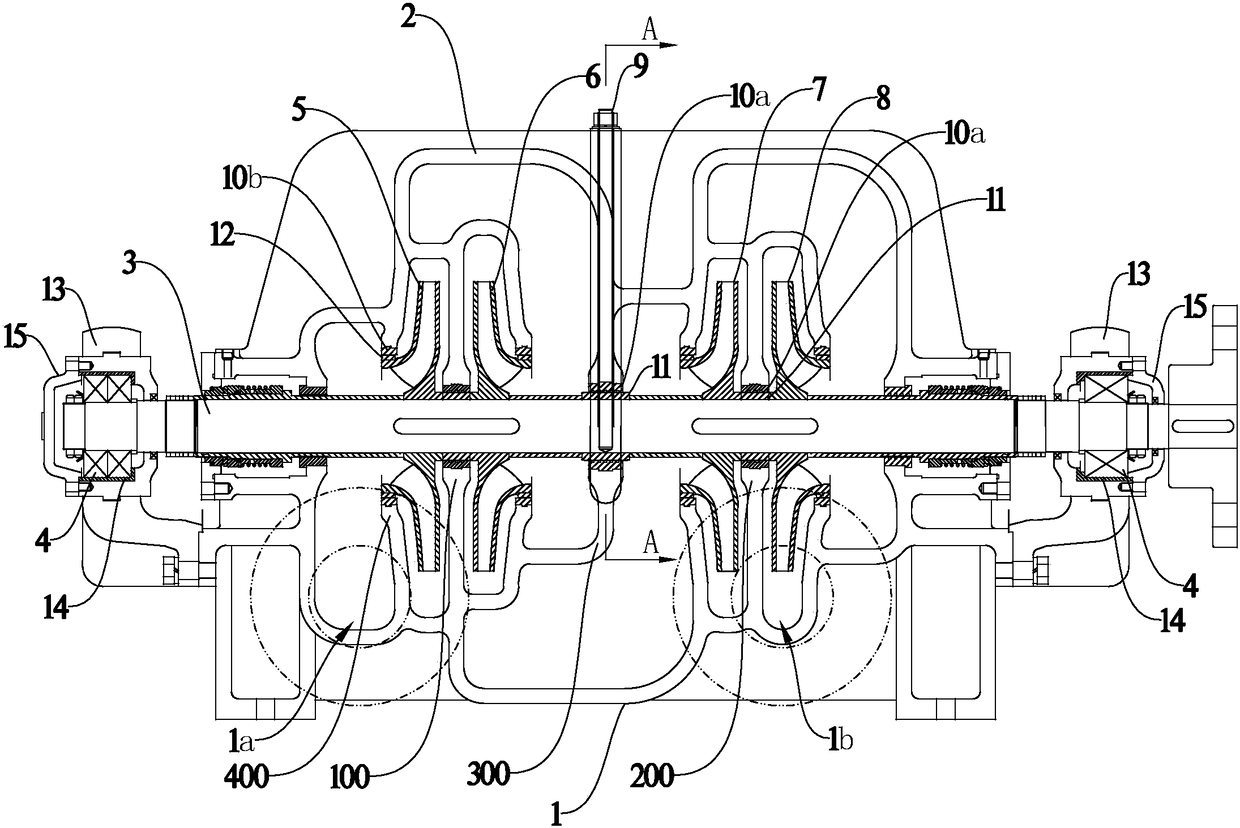
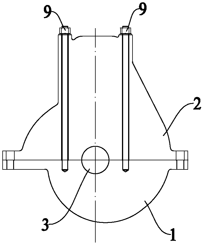
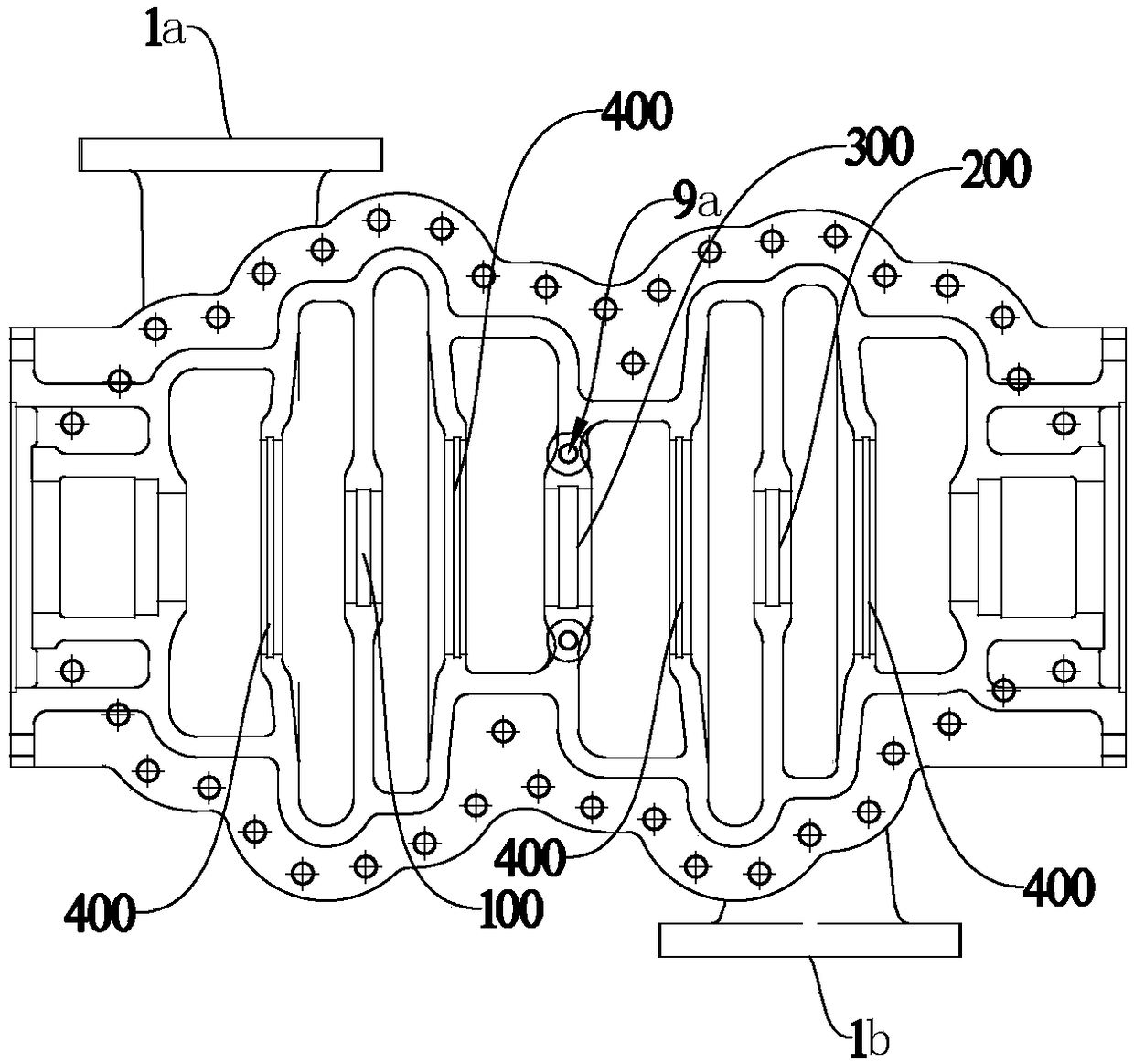
[0017] Such as Figure 1~4 As shown, the embodiment of the present invention includes a pump body 1 and a pump cover 2 that are fixedly connected around. The pump body 1 is provided with a pump inlet 1a and a pump outlet 1b. Two bearing bodies 13 extend from both ends of the pump body 1 respectively. The pump shaft 3 passes through the bearing body 13 , and the bearing 4 is arranged between the pump shaft 3 and the bearing body 13 . The key point is that the first-stage impeller 5, the second-stage impeller 6, the third-stage impeller 7 and the fourth-stage impeller 8 are sequentially fixed on the pump shaft 3, and the first partition wall 100 and the second partition wall 100 extend from the inside of the ...


PUM


Abstract

The invention discloses a novel high-pressure water sealing pump. The novel high-pressure water sealing pump comprises a pump body and a pump cover, wherein the peripheries of the pump body and the pump cover are fixedly connected, a pump inlet and a pump outlet are formed in the pump body, two bearing bodies extend out of the two ends of the pump body correspondingly, a pump shaft penetrates through the bearing bodies, and bearings are arranged between the pump shaft and the bearing bodies; a first-stage impeller, a second-stage impeller, a third-stage impeller and a fourth-stage impeller aresequentially fixed to the pump shaft, a first division wall, a second division wall and an intermediate division wall extend out of the interiors of the pump body and the pump cover, and the first division wall is located between the first-stage impeller and the second-stage impeller; and the second division wall is located between the third-stage impeller and the fourth-stage impeller, the intermediate division wall is located between the second-stage impeller and the third-stage impeller, an intermediate stand column bolt is arranged at the intermediate division wall, and the intermediate stand column bolt penetrates through the pump body and the pump cover. According to the novel high-pressure water sealing pump, the first-stage impeller, the second-stage impeller, the third-stage impeller and the fourth-stage impeller are arranged, the structure is reliable, the airtightness is good, and the service life is long.

Description

technical field [0001] The invention relates to the technical field of water pumps, in particular to sealed water pumps. Background technique [0002] In my country's beach dredging industry, dredgers are widely used for channel dredging, sea blowing, port construction and other projects, and water sealing pumps are key equipment on dredgers. The water seal pump is used to seal water for the shaft seal of the mud pump to prevent mud and sand from entering the shaft seal of the mud pump and protect the normal operation of the mud pump. Whether the sealing water pump can run safely and reliably is directly related to the construction progress and the life of the mud pump. Existing sealing water pumps are generally divided into high-pressure sealing water pumps and low-pressure sealing water pumps. The high-pressure sealing water pump has a high flow rate and a large diameter of the impeller, resulting in an increase in the volume of the shell. Under the same pressure, the cro...

Claims


Application Information

Patent Timeline
IPC IPC(8): F04D1/06F04D29/00F04D29/42F04D29/08F04D29/046
CPCF04D1/06F04D29/007F04D29/046F04D29/086F04D29/426
Inventor 包耀红王健董江军赵妙土向盼盼
Owner 宁波瑞德森船用泵制造有限公司
Why Eureka
Try Eureka