Guide rail photographing device

A shooting device and guide rail technology, which is applied to lighting devices, lighting devices, lighting device components, etc., can solve problems such as slow shooting speed, dark corners, and skewed pictures, and achieve the effect of fast shooting speed and improved work effect

Pending Publication Date: 2018-06-01
JIANGXI HOLITECH TECH
View PDF5 Cites 5 Cited by
  • Summary
  • Abstract
  • Description
  • Claims
  • Application Information

AI Technical Summary

Problems solved by technology

[0002] The existing shooting method uses a simple three-frame angle to fix the signal test box, which cannot guarantee that the camera and the captured ISO resolution Chart are in a horizontal and vertical stat

Method used


Image

  • Guide rail photographing device
  • Guide rail photographing device
  • Guide rail photographing device

Examples


Embodiment Construction

[0018] A specific implementation manner of a photographing device of the present invention will be described below with reference to the accompanying drawings.

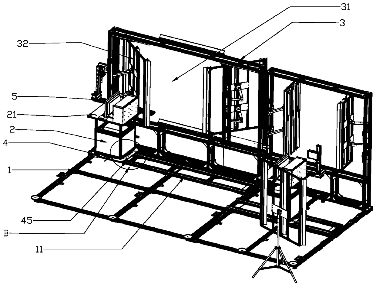
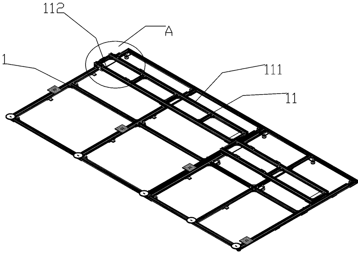
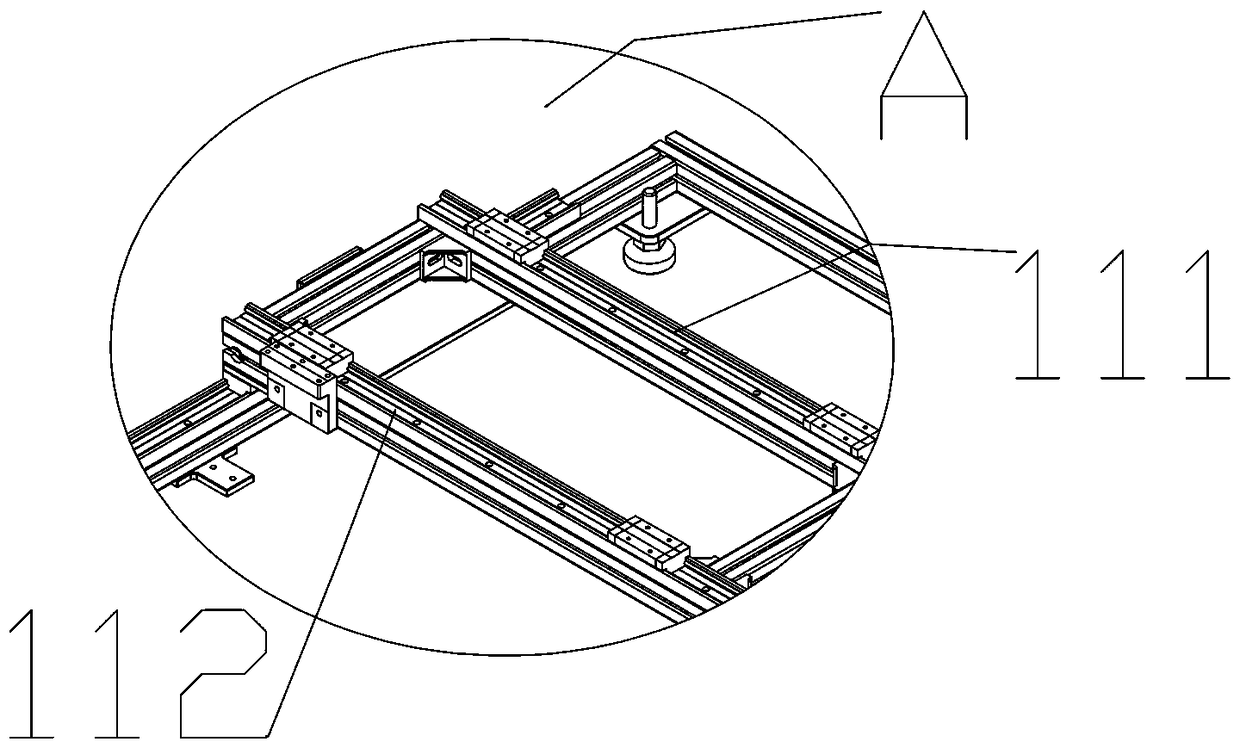
[0019] see figure 1 , a kind of photographing device of the present invention, comprises a bracket, on the bracket through the first slide mechanism 11 can slide left and right or front and back and is connected with a turntable 4, and the turntable 4 is connected with the organic case 2 in rotation, and is fixedly connected with an operation platform 21 on the case 2, The upper end surface of the operating platform 21 can slide left and right or up and down through the second sliding mechanism 5 and is connected with a fine-tuning mechanism 51 for installing a camera.

[0020] After adopting the above structure, compared with the prior art, the guide rail shooting device of the present invention has the following advantages: the shooting device adopts the regional guide rail space design, moves through the sliding gu...


PUM


Abstract

The invention relates to a guide rail photographing device. The guide rail photographing device comprises a support. A rotating plate is connected to the support through a first sliding mechanism in aleft-right or front-back sliding mode. A case is connected to the rotating plate rotationally. An operating platform is fixedly connected to the case. A fine adjustment mechanism for mounting a camera is connected to the upper end face of the operating platform through a second sliding mechanism in a left-right or front-back sliding mode. A photographing hole is formed in the support. A combinedlight source is arranged on each of two sides of the photographing hole. The guide rail photographing device has the advantages that the regional guide rail space design is adopted, and three-dimensional accurate adjustment and positioning can be achieved through guide rail sliding during 360-degree rotation, so that accurate photographing is guaranteed, photographed pictures are not deflected anddeformed, and vignetting is avoided.

Description

technical field [0001] The invention relates to the technical field of photographing devices, in particular to a guide rail photographing device. Background technique [0002] The existing shooting method uses a simple three-frame angle to fix the signal test box, which cannot guarantee that the camera and the captured ISO resolution Chart are in a horizontal and vertical state, resulting in skewed, deformed, vignetting, and reading problems in the captured pictures. There is a 200 TV Line difference between the resolution value and the customer, and the shooting speed is very slow. Contents of the invention [0003] In order to overcome the shortcomings of the above-mentioned prior art, the purpose of the present invention is to provide a guide rail imaging device, which can be precisely positioned and adjusted in a vacuum, and can effectively adjust the uniformity of the glow. [0004] In order to achieve the above object, the present invention adopts the following devi...

Claims


Application Information

Patent Timeline
IPC IPC(8): F16M11/42F16M11/04F21V33/00G03B17/56
CPCG03B17/561F16M11/045F16M11/046F16M11/048F16M11/2085F16M11/2092F16M11/425F21V33/0052
Inventor 周明青
Owner JIANGXI HOLITECH TECH
Why Eureka
Try Eureka