Lighting method for LED illumination light guide plate

A technology of LED lighting and LED light source, which is applied to the light guides of lighting devices, light guides of lighting systems, components of lighting devices, etc. Good uniformity of brightness, improved light distribution efficiency and consistency

Active Publication Date: 2018-06-01
SHANGHAI AVIATION ELECTRIC
View PDF5 Cites 0 Cited by
  • Summary
  • Abstract
  • Description
  • Claims
  • Application Information

AI Technical Summary

Problems solved by technology

At present, the illumination of characters and other information on the light guide plate mainly depends on the experience of the LED light source. The uniformity of the brightness design varies from person to person, and it is difficult to guarantee the consistency. The distribution adjustment of the LED light source is a means to realize the optical path design. The current adjustment The method is to use personnel observation and manual correction for local adjustment or re-lighting, which is not only inefficient, but also has poor adjustment accuracy, which will cause unnecessary scrapping and repeated design

Method used


Image

  • Lighting method for LED illumination light guide plate
  • Lighting method for LED illumination light guide plate
  • Lighting method for LED illumination light guide plate

Examples


Embodiment Construction

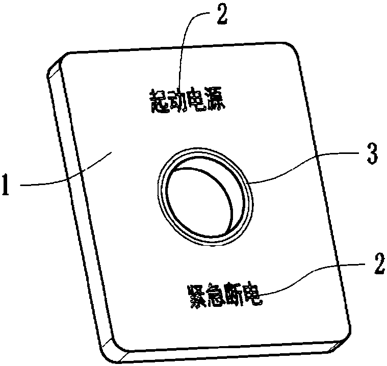
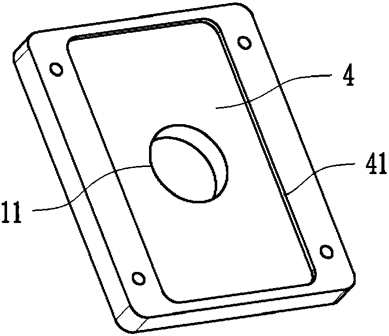
[0019] This see Figure 1 to Figure 6 , shown in the figure is a specific embodiment of a light distribution structure and method for an LED lighting light guide plate, including a light guide panel 1 , characters 2 , engraved lines 3 and a sunken surface area 4 . Wherein, the characters 2 and the engraved lines 3 are placed on the front of the light guide panel 1, and the characters 2 and the engraved lines 3 need to emit light; The back of the panel 1 is used for accommodating the light source circuit board. The present invention is characterized in that the following lighting steps are performed in sequence:

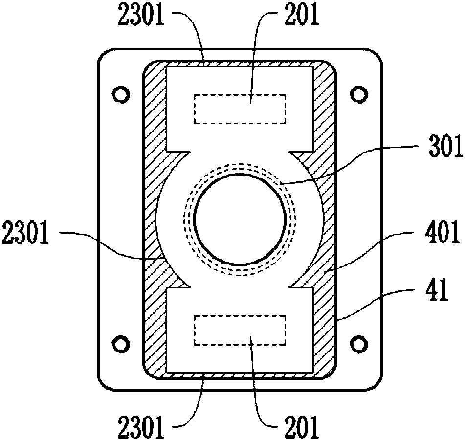
[0020] Step 1. According to the back structure of the light guide panel 1, the inner contour line 11 and the outer contour line 41 are formed by shape offset, and the area included by the inner contour line 11 and the outer contour line 41 is for accommodating light sources plate sink area 4, see figure 2 ;

[0021] Step 2: In the sunken surface area 4, obtain th...


PUM


Abstract

A lighting method for an LED illumination light guide plate includes: a first step, forming an inner contour line and an outer contour line through shape offset according to a back surface structure of the light guide plate, wherein an area included in the inner contour line and the outer contour line is a sinking area for holding a light source circuit board; a second step, mapping light-emittingareas of front surface characters and scribed lines of the light guide plate to the sinking area, and shifting frame lines of the light-emitting areas outward at equal distances by a size R1, whereinthe outer contour line is an inner edge limiting line of an LED light source center; taking a complementary set between an area included in the inner edge limiting line of the LED light source centerand an area included in the outer contour line of the sinking area, and forming an area A; shifting the inner contour line and the outer contour line of the sinking area inward by a size R2 respectively to form an inner offset contour line and an outer offset contour line, wherein an area included in the inner offset contour line and the outer offset contour line is an area B, and the outer offset contour line is an outer edge limiting line of the LED light source center; and a third step, extracting an intersection between the area A and the area B, and forming a lighting range C of the LEDlight source center. The lighting efficiency and the consistency of the LED light sources on the light guide plate are improved.

Description

technical field [0001] The invention belongs to the technical field of light distribution design and relates to a light distribution method for LED lighting light guide plates. Background technique [0002] The light guide plate is an important unit for information display and lighting such as characters in the aircraft cockpit. The uniformity of its lighting brightness directly affects the readability of information and the reading pressure of pilots. The light guide plate includes a light guide panel, characters, engraved lines and sunken areas. Wherein, the characters and the engraved lines are placed on the front of the light guide panel, and the characters and the engraved lines need to emit light; the sunken surface area is placed on the back of the light guide panel for accommodating the light source circuit board. At present, the illumination of characters and other information on the light guide plate mainly depends on the experience of the LED light source. The un...

Claims


Application Information

Patent Timeline
Patent Type & Authority Applications(China)
IPC IPC(8): F21K9/61F21V8/00F21Y115/10
CPCF21V2200/20
Inventor 郑子明范佳栋杨广寿
Owner SHANGHAI AVIATION ELECTRIC
Why Eureka
Try Eureka