Dynamic monitoring devices for CO leakage of sintering equipment and monitoring method

A technology for dynamic monitoring and sintering equipment, applied in furnace safety devices, lighting and heating equipment, furnaces, etc., can solve the problems of occupying operating space, sintering equipment operating space, and cumbersomeness, and achieve small operating space occupation and simple monitoring method , the effect of broad market prospects

Active Publication Date: 2018-06-01
ZHONGYE-CHANGTIAN INT ENG CO LTD
View PDF6 Cites 2 Cited by
  • Summary
  • Abstract
  • Description
  • Claims
  • Application Information

AI Technical Summary

Problems solved by technology

[0005] 1. Small monitoring range: In the existing technology, a CO detector is generally installed at a certain point of the equipment. This method can only monitor the relevant parameters of a small part of the sintering equipment area. The monitoring range is very small and cannot reflect the real situation. Reduce the safety factor of sintering equipment, which brings great hidden dangers to the personal safety of operators
However, if CO detectors are installed at multiple points of the sintering equipment, the cost will be too high and the operating space of the sintering equipment will be greatly reduced
[0006] 2. Occupy the operating space of the sintering equipment: the CO detector needs to be connected with the signal cable and the power cable to operate normally, and the cable needs to be covered with steel pipes. These additional equipment will greatly occupy the limited operating space, and when the operator is operating, It is very easy to trip over the steel pipe with the cable jacket and cause production accidents
[0007] 3. Unable to predict the location of CO leakage: under the existing technology, when the CO detector detects CO leakage, the system cannot predict the location of CO leakage
If you want to know the CO leakage point, the operator has to take a portable CO detector to test the location one by one, which is cumbersome and increases the labor intensity

Method used


Image

  • Dynamic monitoring devices for CO leakage of sintering equipment and monitoring method
  • Dynamic monitoring devices for CO leakage of sintering equipment and monitoring method
  • Dynamic monitoring devices for CO leakage of sintering equipment and monitoring method

Examples


Embodiment

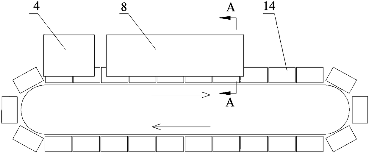
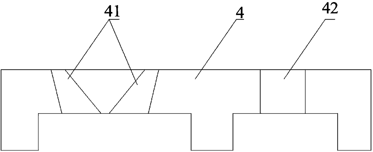
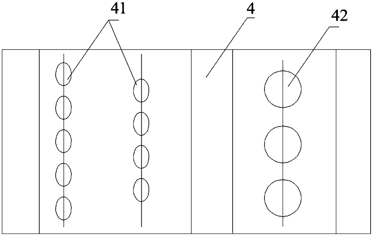
[0049] like Figure 1-3 , Image 6 As shown, the dynamic monitoring device for CO leakage of sintering equipment in this embodiment, the sintering equipment includes an ignition furnace 4, a gas injection device 8 and a sintering equipment trolley 14, and the ignition furnace 4 includes two rows of ignition burners 41 and a row of heat preservation burners. nozzle 42 , the gas injection device 8 includes a gas injection cover 81 and a gas injection pipeline 82 . At least one set of dynamic monitoring device is provided. The dynamic monitoring device includes a patrol device 1, a CO detector 21 and a controller 3. The patrol device 1 includes a patrol robot 11, a driving device and is arranged on the top of the ignition furnace 4 and / or the gas injection hood. The track 12 at the top of 81, the CO detector 21 is installed on the patrol robot 11, and the patrol robot 11 runs on the track 12 under the drive of the driving device, and the CO detector 21 will be installed on the t...


PUM


Abstract

The invention discloses dynamic monitoring devices for CO leakage of sintering equipment. The sintering equipment comprises an ignition furnace, a gas injection device and a sintering equipment trolley, and at least one set dynamic monitoring device is arranged; each dynamic monitoring device comprises a patrol device, a CO detector and a controller, and each patrol device comprises a patrol robot, a driving device and tracks, the tracks are arranged at the furnace top of the ignition furnace and / or the top of a gas injection hood, and the CO detectors are mounted on the patrol robots; and thepatrol robots run on the tracks under driving of the driving devices, and the CO detectors transmit a monitoring signal received at the furnace top of the ignition furnace and / or the top of the gas injection hood to the controller in real time. The invention further provides a monitoring method of the dynamic monitoring devices. According to the dynamic monitoring devices, the monitoring range islarge, the occupied operation space is small, the monitoring method is simple and convenient, and the monitoring efficiency is high.

Description

technical field [0001] The invention belongs to the field of sintering equipment, and in particular relates to a dynamic monitoring device and a monitoring method for dangerous situations of sintering equipment. Background technique [0002] The sintering process is a key link in the ironmaking process. Its principle is to mix various powdery iron-containing raw materials with an appropriate amount of fuel and solvent, add an appropriate amount of water, and after mixing and pelletizing, the materials are generated on the sintering equipment. A series of physical and chemical changes, sintered into blocks, which are sent to the blast furnace for the next step. In the modern sintering process, the ignition furnace is used to provide a high-temperature ribbon flame to the surface of the mixture, so that the solid fuel in it is ignited and burned, and the surface mixture is sintered under the heat release of the high-temperature flue gas of the ignition furnace and the solid fu...

Claims


Application Information

Patent Timeline
Patent Type & Authority Applications(China)
IPC IPC(8): F27D21/00C22B1/22
CPCC22B1/22F27D21/00F27D2021/0057
Inventor 周浩宇向锡炎刘前
Owner ZHONGYE-CHANGTIAN INT ENG CO LTD
Why Eureka
Try Eureka