Measurement device and method for simulation air compressor in working state

A technology of measuring device and working state, applied in mechanical measuring device, measuring device, using mechanical device, etc., can solve the problems of low assembly efficiency and long engine assembly cycle, and achieve the effect of improving measurement accuracy

Active Publication Date: 2018-06-01
CHINA HANGFA SOUTH IND CO LTD
View PDF5 Cites 14 Cited by
  • Summary
  • Abstract
  • Description
  • Claims
  • Application Information

AI Technical Summary

Problems solved by technology

[0010] The invention provides a measuring device and measuring method for simulating the working state of the compressor to solve the problem that the measuring method of the rotor assembly of the turboshaft engine compressor is easily affected by uncontrollable factors in the process of changing jobs, the engine assembly period is long, and the assembly efficiency is low. low technical issues

Method used


Image

  • Measurement device and method for simulation air compressor in working state
  • Measurement device and method for simulation air compressor in working state
  • Measurement device and method for simulation air compressor in working state

Examples


Embodiment Construction

[0030] The embodiments of the present invention will be described in detail below with reference to the accompanying drawings, but the present invention can be implemented in various ways defined and covered below.

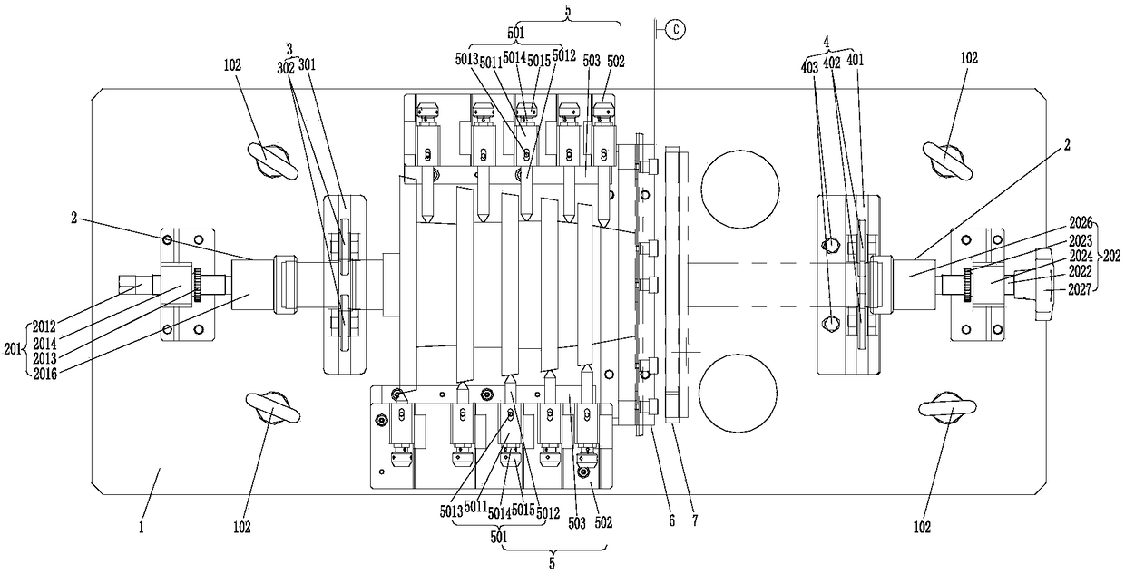
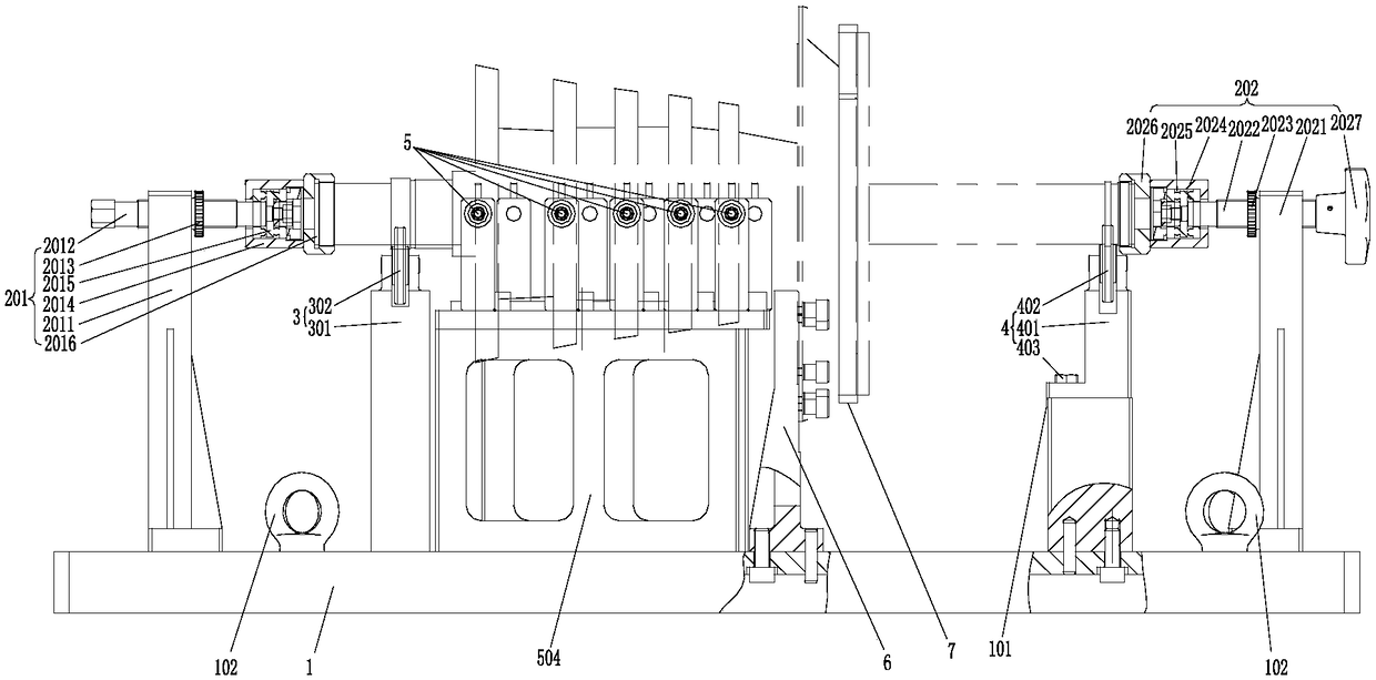
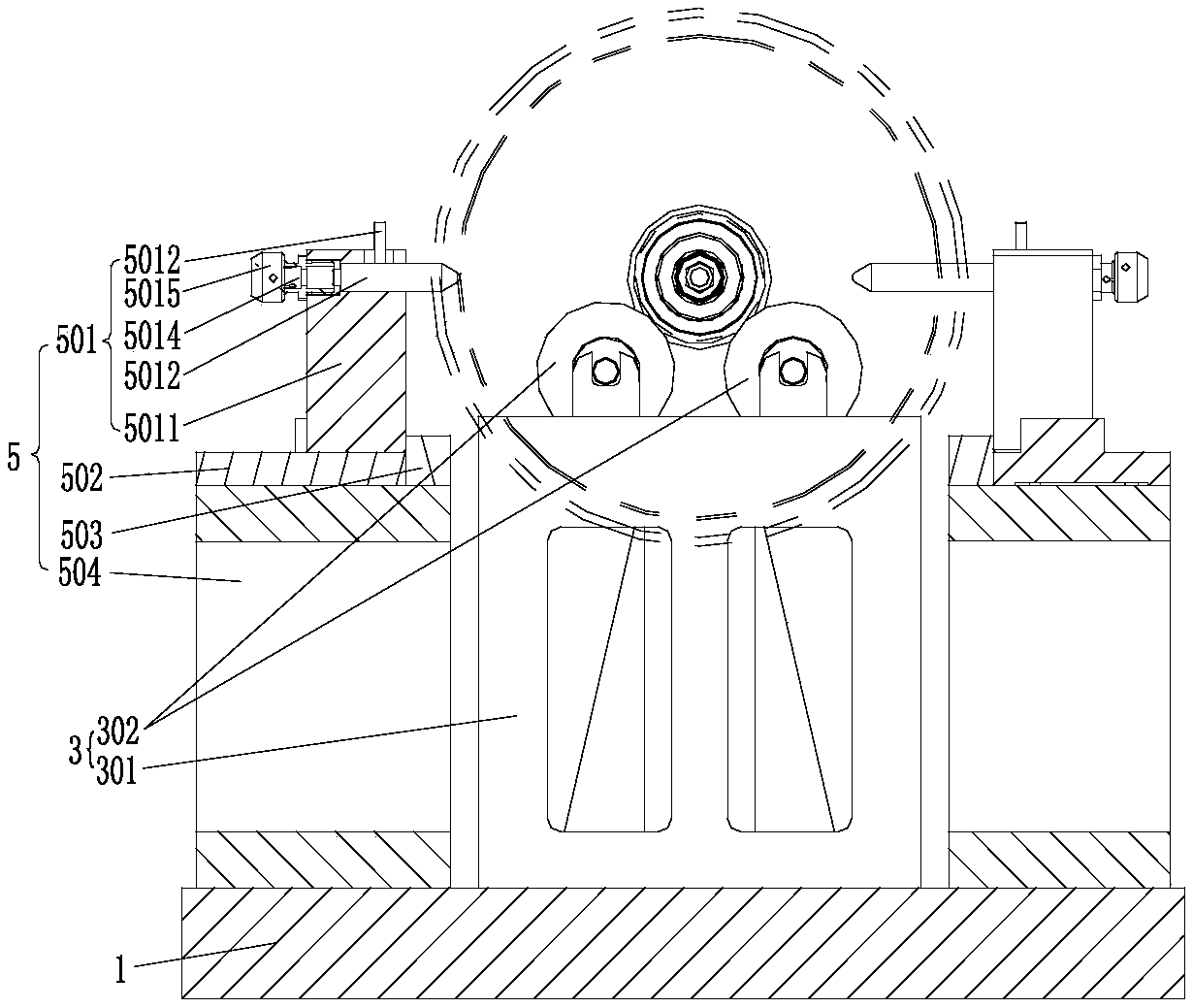
[0031] figure 1 It is one of the structural schematic diagrams of the measuring device under the working state of the simulated compressor in the preferred embodiment of the present invention; figure 2 It is the second structural diagram of the measuring device under the working state of the simulated compressor in the preferred embodiment of the present invention; image 3 It is the third structural diagram of the measuring device under the working state of the simulated compressor in the preferred embodiment of the present invention, Figure 4 It is a structural schematic diagram of the pair of watch parts in the preferred embodiment of the present invention.

[0032] Such as figure 1 As shown, the measurement device of the simulated compressor working state...


PUM


Abstract

The invention discloses a measurement device and method for a simulation air compressor in a working state. The measurement device comprises a bottom plate, and the bottom plate is provided with an end part assembly module, a first bearing mechanism which is used for bearing a first end journal of an air compressor rotor assembly from the bottom of the air compressor rotor assembly, and a second bearing mechanism which is used for bearing a second end journal of the air compressor rotor assembly from the bottom of the air compressor rotor assembly, and carrying out the axial and/or radial finetuning and control of a bearing position. A measurement mechanism and a positioning plate are disposed between the first bearing mechanism and the second bearing mechanism, wherein the measurement mechanism is corresponding to centrifugal impellers of the air compressor rotor assembly and the parts between the adjacent centrifugal impellers and is used for measuring the jump values of blade tipsof the centrifugal impellers, the wheel hubs of the centrifugal impellers and an air compressor rotor shaft in a rotating process, and the positioning plate is attached to a reference surface of the air compressor rotor assembly so as to form a measurement reference of the measurement mechanism.

Description

technical field [0001] The invention relates to the technical field of aero-engine simulation measurement, in particular to a measurement device for simulating the working state of an air compressor. In addition, the present invention also relates to a measurement method based on the simulated compressor working state, which includes the above-mentioned measuring device under the simulated compressor working state. Background technique [0002] The compressor components of a new turboshaft engine are composed of a compressor rotor assembly and a compressor axial casing assembly. The rotor assembly is a single-rotor structure with five axial flow stages and one centrifugal stage. The compressor axial flow casing assembly is composed of a compressor casing and stator blades. The stator blades are non-rotatable parts of the compressor. The stator blades of the compressor casing assembly and the compressor rotor blades are arranged in a staggered manner to form an airflow chann...

Claims


Application Information

Patent Timeline
Patent Type & Authority Applications(China)
IPC IPC(8): G01B5/08G01B5/00
CPCG01B5/00G01B5/08
Inventor 李同瞿品祥秦健黄志斌盛波刘海燕
Owner CHINA HANGFA SOUTH IND CO LTD
Why Eureka
Try Eureka