User fault positioning method and device

A fault location and fault technology, applied in the field of user fault location methods and devices, can solve the problem of low user efficiency in locating faults

Active Publication Date: 2018-06-01
STATE GRID BEIJING ELECTRIC POWER +1
View PDF8 Cites 3 Cited by
  • Summary
  • Abstract
  • Description
  • Claims
  • Application Information

AI Technical Summary

Problems solved by technology

[0004] Embodiments of the present invention provide a method and device for locating user faults, so as to at least solve

Method used


Image

  • User fault positioning method and device
  • User fault positioning method and device

Examples


Embodiment Construction

[0019] In order to enable those skilled in the art to better understand the solutions of the present invention, the following will clearly and completely describe the technical solutions in the embodiments of the present invention in conjunction with the drawings in the embodiments of the present invention. Obviously, the described embodiments are only It is an embodiment of a part of the present invention, but not all embodiments. Based on the embodiments of the present invention, all other embodiments obtained by persons of ordinary skill in the art without making creative efforts shall fall within the protection scope of the present invention.

[0020] It should be noted that the terms "first" and "second" in the description and claims of the present invention and the above drawings are used to distinguish similar objects, but not necessarily used to describe a specific sequence or sequence. It is to be understood that the data so used are interchangeable under appropriate ...


PUM


Abstract

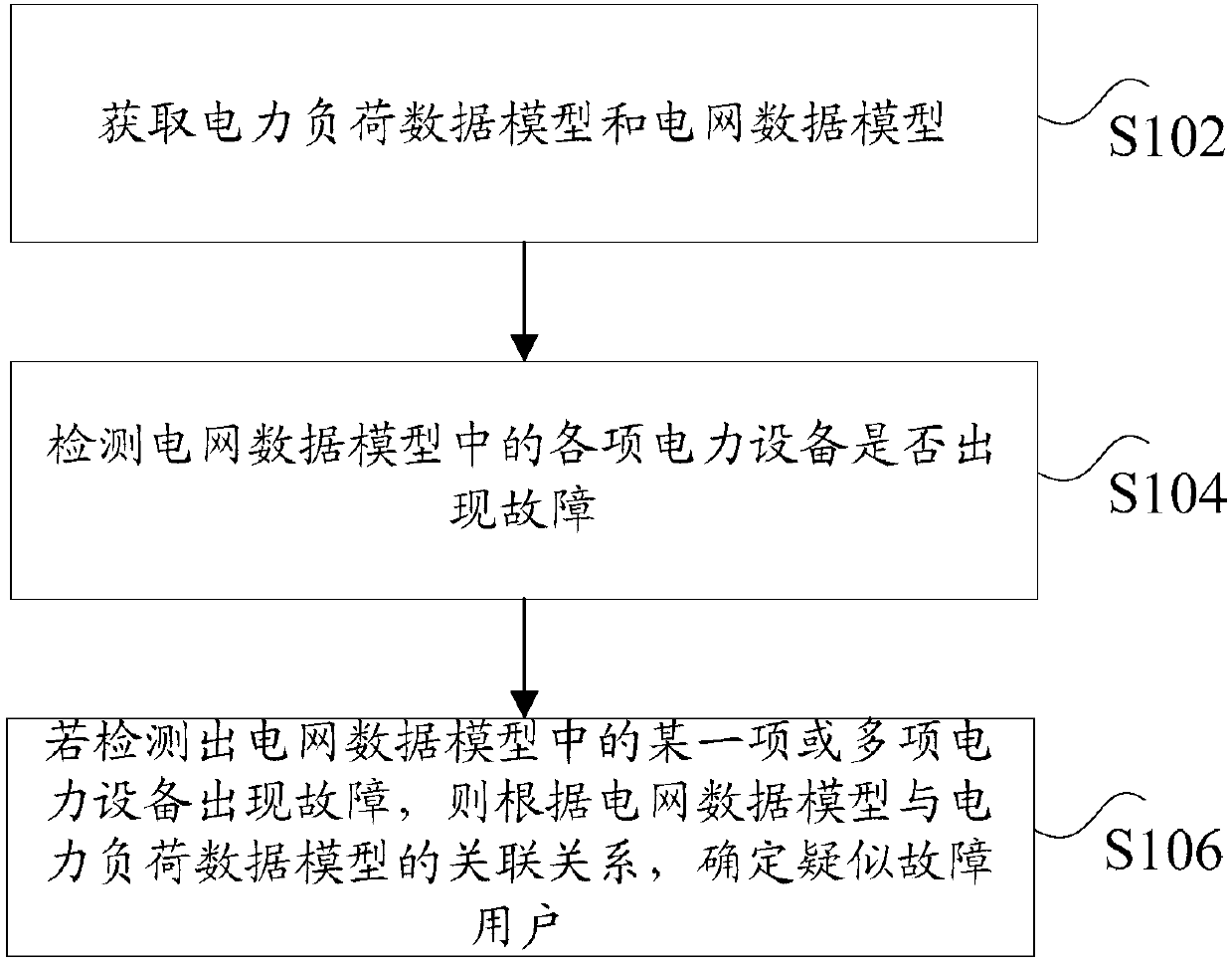
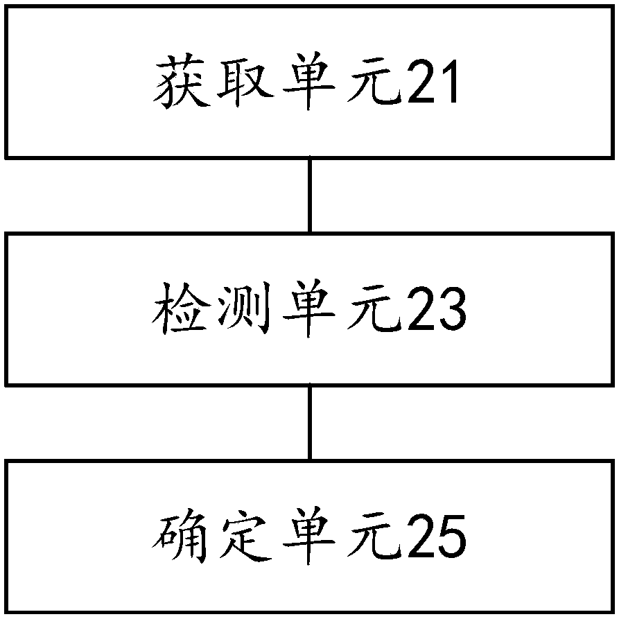
The invention discloses a user fault positioning method and a user fault positioning device. The User fault positioning method comprises the steps of: acquiring a power load data model and a power grid data model, wherein the power load data model is a model established according to power grid information data of target users, and the power grid data model is a model established according to powerequipment operation data relevant to each target user, and an association relationship exists between the power grid data model and the power load data model; detecting whether power equipment in thepower grid data model fails; and determining a suspected fault user according to the association relationship exists between the power grid data model and the power load data model when detecting that one or multiple sets of power equipment in the power grid data model fails, wherein the suspected fault user is a user corresponding to the failed power equipment. The user fault positioning methodand the user fault positioning device solve the technical problem of low efficiency of positioning fault users when dealing with power system failures in the related technologies.

Description

technical field [0001] The invention relates to the field of electric power technology, in particular to a user fault location method and device. Background technique [0002] In related technologies, when determining the scope of influence of equipment failure in the power system, the scope of influence of the failed power equipment is generally manually analyzed, and the analysis efficiency is low and the analysis time is relatively long. In the current power system, it generally includes plants, stations and operating lines. Among them, plants and stations generally include switches, switches, busbars, transformers, generators, capacitors, load lines and other equipment. The relationship between plants and stations is connected by power operating lines. To form a network topology, the power equipment is connected with switches and switches to form a plant station topology. When a fault occurs on the operating line in the power system, it is necessary to determine the loc...

Claims


Application Information

Patent Timeline
IPC IPC(8): G01R31/08
CPCG01R31/086Y04S10/52
Inventor 魏妍萍张宏志张杨汤恩洪岳兵董禹泽胡雨时
Owner STATE GRID BEIJING ELECTRIC POWER
Why Eureka
Try Eureka