Single image defogging method and device based on bilateral filtering and median filtering

A bilateral filtering, single-image technology, applied in image enhancement, image analysis, image data processing, etc., can solve the problem that the operation speed needs to be improved, achieve the advantage of operation speed, ensure image quality, and avoid the effect of image color oversaturation

Inactive Publication Date: 2018-06-01
QILU UNIV OF TECH
View PDF6 Cites 3 Cited by
  • Summary
  • Abstract
  • Description
  • Claims
  • Application Information

AI Technical Summary

Problems solved by technology

However, the calculation speed of

Method used


Image

  • Single image defogging method and device based on bilateral filtering and median filtering
  • Single image defogging method and device based on bilateral filtering and median filtering
  • Single image defogging method and device based on bilateral filtering and median filtering

Examples


Embodiment 1

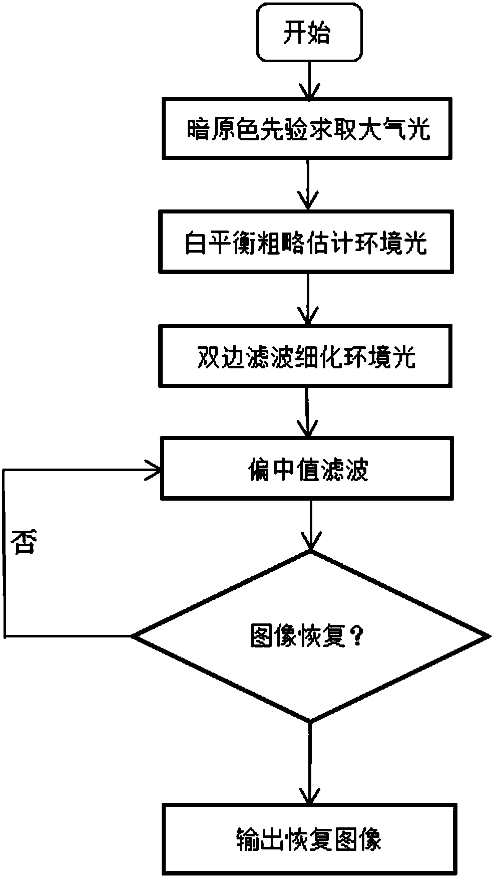
[0047] This embodiment discloses a single image defogging method based on bilateral filtering and median filtering, such as figure 1 shown, including the following steps:

[0048] Step 1: Estimate the atmospheric light value based on the dark channel prior;

[0049] Step 1.1: Obtain the dark channel prior map of the foggy image;

[0050] Step 1.2: Under a certain principle, select the brightness value of the pixel in the image that is similar to the atmospheric light intensity when the image was taken as the atmospheric light intensity, and select the 0.1% pixel point with the largest dark channel value;

[0051] Step 1.3: Search the image for the maximum brightness value given in step 1.2, and use this point as the atmospheric light value A.

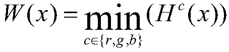
[0052] The expression for the dark channel is given below:

[0053]

[0054] where G v Represents a single channel of a color image, r, g, b are the three primary color channels, and α(x) is a window centered on x.

[0055] Step...

Embodiment 2

[0115] The purpose of this embodiment is to provide a computing device.

[0116] An image defogging device for bilateral filtering and median filtering, comprising a memory, a processor, and a computer program stored in the memory and operable on the processor, and the processor implements the following steps when executing the program, including:

[0117] Step 1: Estimate the atmospheric light value based on the dark channel prior for the original foggy image;

[0118] Step 2: According to the atmospheric light value, use bilateral filtering to roughly estimate the ambient light;

[0119] Step 3: performing median filtering on the ambient light to obtain improved ambient light;

[0120] Step 4: Restoring the original hazy image based on atmospheric light values ​​and improved ambient light.

Embodiment 3

[0122] The purpose of this embodiment is to provide a computer-readable storage medium.

[0123] A computer-readable storage medium, on which a computer program is stored, and when the program is executed by a processor, the following steps are performed:

[0124] Step 1: Estimate the atmospheric light value based on the dark channel prior for the original foggy image;

[0125]Step 2: According to the atmospheric light value, use bilateral filtering to roughly estimate the ambient light;

[0126] Step 3: performing median filtering on the ambient light to obtain improved ambient light;

[0127] Step 4: Restoring the original hazy image based on atmospheric light values ​​and improved ambient light.


PUM


Abstract

The invention discloses a single image defogging method and a single image defogging device based on bilateral filtering and median filtering. The single image defogging method comprises the steps of:estimating an atmospheric light value of an original foggy image based on dark channel priori; adopting bilateral filtering for estimating ambient light roughly according to the atmospheric light value; performing median filtering on the ambient light to obtain improved ambient light; and restoring the original foggy image based on the atmospheric light value and the improved ambient light. The single image defogging method combines the advantages of bilateral filtering and median filtering, can fully avoid color oversaturation of the image and a halo effect of image edges, and can effectively deal with the foggy image impurities at the edges and corners.

Description

technical field [0001] The invention belongs to the field of image enhancement, in particular to a single image defogging method and device based on bilateral filtering and median filtering. Background technique [0002] In haze and dense fog conditions, the image we get is a weakened image after being absorbed and scattered by impurity particles in the air. In this case, the visibility, resolution and color saturation of the image obtained will greatly deviate from the true value, which is not conducive to the extraction of image features, so that people make wrong results for various situations. Therefore, it is of great significance and application significance to conduct dehazing research in various fields. [0003] Image dehazing research is a research of great research significance in our daily life. Many researches on dehazing problems not only require the original image with fog itself, but also require researchers to collect some images in non-fogged weather. The ...

Claims


Application Information

Patent Timeline
IPC IPC(8): G06T5/00G06T5/10G06T7/13G06T7/90
CPCG06T5/001G06T5/10G06T7/13G06T7/90G06T2207/20028G06T2207/20032
Inventor 李爱民李晓聪孙涛王新刚
Owner QILU UNIV OF TECH
Why Eureka
Try Eureka