Cylindrical power battery module

A technology for power batteries and battery modules, which is applied to battery components, secondary batteries, circuits, etc., can solve the problems of reducing battery life, affecting the service life of power batteries, and uneven temperature distribution of batteries, so as to improve temperature distribution Consistency, improved heat exchange efficiency, and reduced risk of thermal runaway

Active Publication Date: 2018-06-01
NANJING UNIV OF AERONAUTICS & ASTRONAUTICS
View PDF3 Cites 7 Cited by
  • Summary
  • Abstract
  • Description
  • Claims
  • Application Information

AI Technical Summary

Problems solved by technology

However, with the increase of battery energy storage density, the problem of thermal stability becomes more prominent. Excessively high or low temperature and uneven temperature distribution between batteries will directly affect the service life and performance of the power battery, and lead to safety problems of the battery system.
[0005] The thermal management goal of the power battery is to deal with the heat of the battery in a timely manner and control the battery temperature within a safe range. At present, the thermal management methods of the power battery mainly include air cooling, liquid cooling, and phase change material cold storage. For cylindrical power batteries, due to The complexity of the structure of the battery module and the complex thermal management scheme will increase the cost and cause safety hazards. Many companies do not have a thermal management scheme for cylindrical power batteries, and only rely on the natural heat dissipation of the battery module, which will reduce the life of the battery. , a serious risk of explosion due to thermal runaway
[0006] In summary, there is a lack of a battery module in the prior art, which can dissipate heat naturally, reduce the temperature rise of the battery, and improve the consistency of the temperature difference between the batteries.

Method used


Image

  • Cylindrical power battery module
  • Cylindrical power battery module
  • Cylindrical power battery module

Examples


Embodiment Construction

[0036] In order to enable those skilled in the art to better understand the technical solutions of the present invention, the present invention will be further described in detail below in conjunction with specific embodiments.

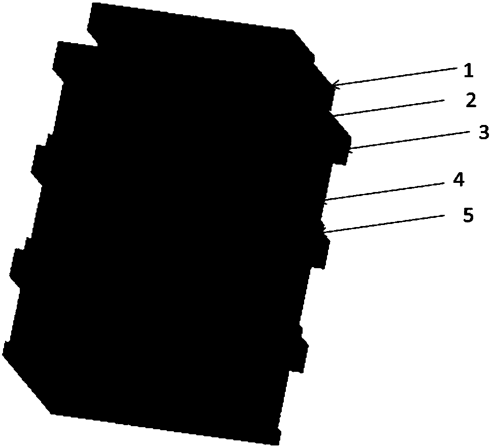
[0037] Embodiments of the present invention provide a cylindrical power battery module, such as figure 1 and figure 2 As shown, it includes a ventilation device 1 , a ventilation pipe 2 , a fixed plate 3 at the top of the battery pack, a battery module 4 , and a fixed plate 5 at the bottom of the battery.

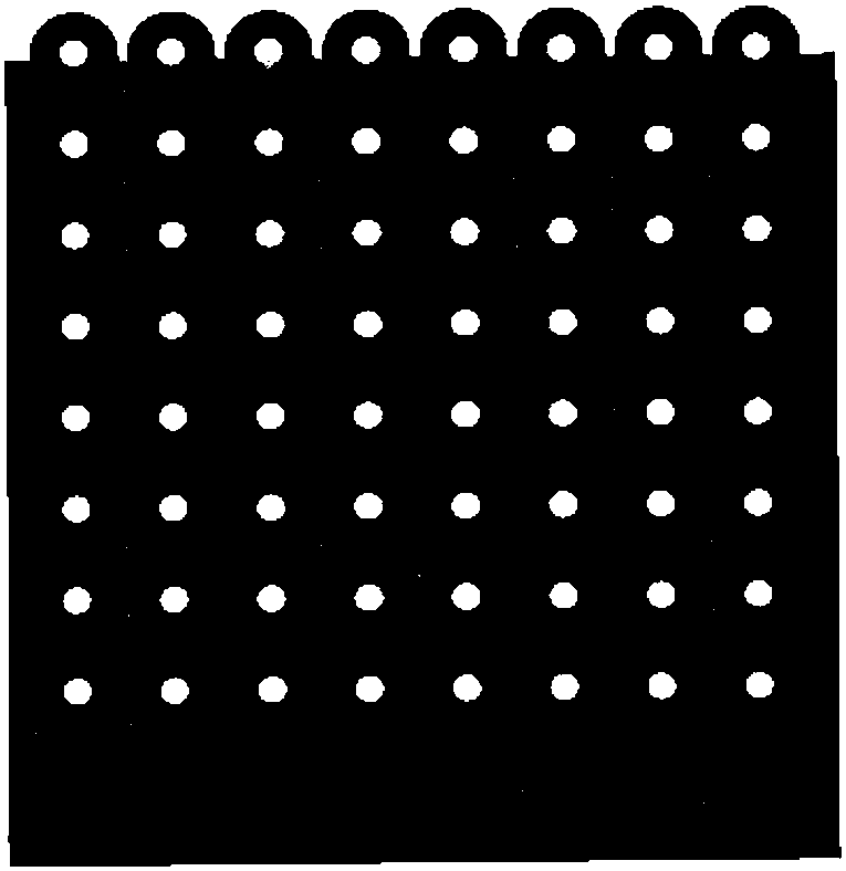
[0038] The bottom surface of the battery module 4 is fixed on the battery bottom fixing plate 5, the top of the battery module 4 is fixed on the battery top fixing plate 3, the battery module 4 is composed of cylindrical batteries arranged in rows and rows, and the cylindrical batteries Install vent pipe 2 in the gap between, such as image 3 and Figure 5 shown.

[0039] A through hole is set on the pipe of the ventilation pipe 2, such as F...


PUM


Abstract

The invention discloses a cylindrical power battery module, and relates to the technical field of power battery heat management. The cylindrical power battery module comprises a ventilating device, breathing pipes, a battery pack top fixing disc, a battery module and a battery bottom fixing disc; the bottom surface of the battery module is fixed to the battery bottom fixing disc; the end of the battery module is fixed to the battery pack top fixing disc; the battery module consists of cylindrical batteries which are arranged neatly in lines and rows; the breathing pipes are mounted at gaps among the cylindrical batteries; through holes are formed in pipe bodies of the breathing pipes; one end of each breathing pipe is closed, and the other end of each breathing pipe is connected with the ventilating device in a closed manner; the ventilating device is mounted at the top of the battery pack top fixing disc; and a temperature sensor is arranged in the battery pack. The cylindrical powerbattery module is applicable to the technical field of power battery heat management, and can effectively reduce the temperature rise of the batteries of the battery pack, and improve the temperaturedifference consistency of various batteries of the power battery module.

Description

technical field [0001] The invention relates to the technical field of power battery thermal management, in particular to a cylindrical power battery module. Background technique [0002] As a non-renewable energy source, oil reserves will gradually decrease as people use it. The widespread use of automobiles consumes a large amount of oil, aggravates the emission of greenhouse gases, and increases the pressure of energy crisis and environmental pollution. Therefore, it has become a national strategy to develop new energy sources and find energy sources to replace petroleum in automotive applications. [0003] As the development trend of future transportation, electric vehicles are favored by people for their environmental protection, energy saving, and portability. They have gradually become the focus of attention in the world. As the heart of electric vehicles, power batteries and battery management systems restrict the development of new energy vehicles. , is a key node...

Claims


Application Information

Patent Timeline
Patent Type & Authority Applications(China)
IPC IPC(8): H01M2/10H01M10/613H01M10/617H01M10/625H01M10/635H01M10/6561H01M50/20
CPCH01M10/613H01M10/617H01M10/625H01M10/635H01M10/6561H01M50/20Y02E60/10
Inventor 周浩兵周飞周其鹏
Owner NANJING UNIV OF AERONAUTICS & ASTRONAUTICS
Why Eureka
Try Eureka