
A magnetic fluid liquid cooling plate, a liquid cooling system composed of the same, and a control method thereof

A liquid-cooling plate, magnetic fluid technology, applied in electrical components, electrochemical generators, secondary batteries, etc., can solve the problems of abnormal rise in module temperature, high temperature, and inability to accurately and effectively reduce module temperature, etc. Achieve the effect of improving service life and performance, and improving the consistency of temperature distribution

Active Publication Date: 2020-09-25
JIANGSU UNIV
View PDF7 Cites 0 Cited by
  • Summary
  • Abstract
  • Description
  • Claims
  • Application Information

AI Technical Summary

Problems solved by technology

[0005] In view of the above shortcomings of the existing technology: multiple modules are arranged side by side in the battery pack, and the temperature of the middle module is higher than that of the modules on both sides; The temperature of the module rises abnormally, and the temperature of the module cannot be accurately and effectively reduced; the present invention adopts the following design:

Method used


Image

  • A magnetic fluid liquid cooling plate, a liquid cooling system composed of the same, and a control method thereof
  • A magnetic fluid liquid cooling plate, a liquid cooling system composed of the same, and a control method thereof
  • A magnetic fluid liquid cooling plate, a liquid cooling system composed of the same, and a control method thereof

Examples


Embodiment Construction

[0027] The structure and working principle of a liquid cooling device based on a variable magnetic fluid channel of the present invention will be further described below in conjunction with the accompanying drawings.

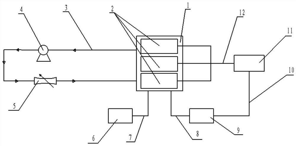
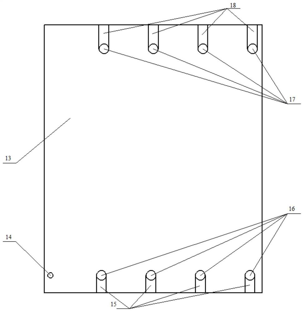
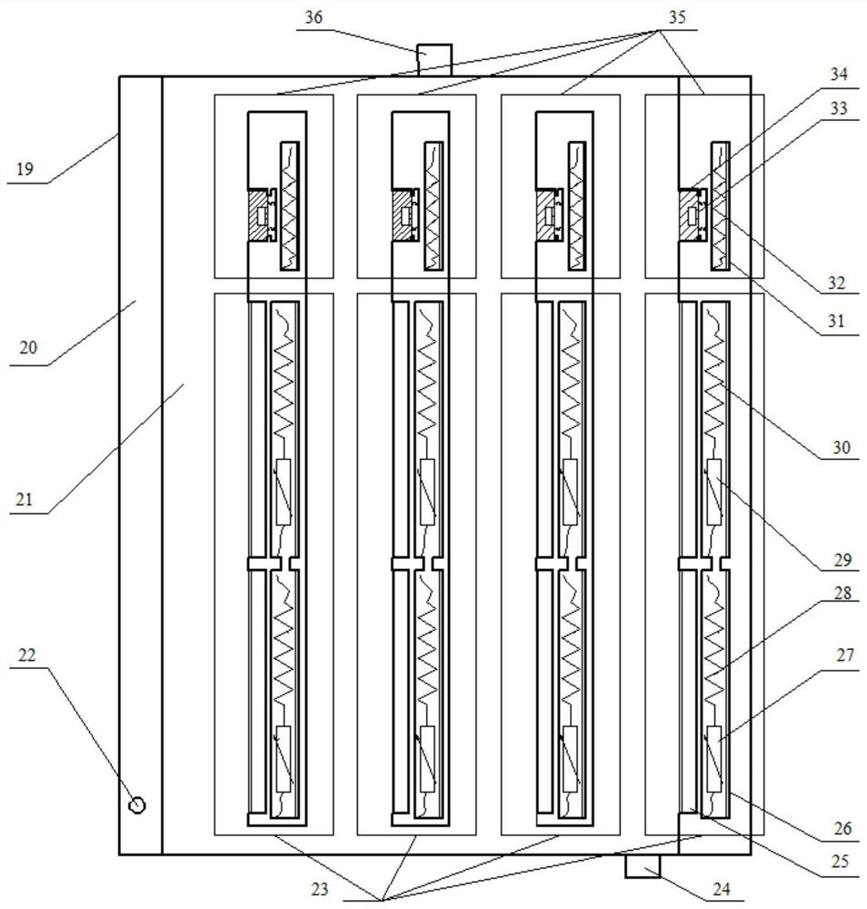
[0028] Such as figure 1 As shown, a liquid cooling system based on a variable magnetic fluid flow channel in the present invention includes a battery module subsystem, a coolant circulation subsystem and a flow channel control subsystem. The battery module subsystem includes a battery module 2 and a BMS11, the temperature information collection line 12 transmits battery temperature information, the coolant circulation subsystem includes a liquid cooling plate 1, a water pump 4 and a discharge valve 5, which are connected through a liquid cooling pipeline 3, and the flow channel control subsystem includes an external power supply 6. The magnetic fluid controller 9 and the liquid cold plate 1 are connected inside the subsystem through the power line 7 and the cont...


PUM


Abstract

The invention discloses a magnetofluid liquid cooling plate, a liquid cooling system applied to a high-speed train emergency power supply constructed by the magnetofluid liquid cooling plate and a liquid cooling control method of the liquid cooling system. In an operation process of the liquid cooling system, a controller is used for controlling flow and flowing state of cooling liquid in the liquid cooling plate in real time according to temperature information of battery modules; the flow control is characterized by supplying power to magnetic field generation devices at upper parts of otherflowing channel partition plates through an external power supply to generate electric fields, then pushing movable sliding blocks filled with magnetofluid into flowing channels through magnetic fields so as to seal other flowing channels and increase the flow in corresponding flowing channel of the battery pack; the flowing state control is characterized by supplying power to lower magnetic field generation devices of other flowing channel partition plates through the external power supply to generate magnetic fields; the magnetic fields are used for pushing film-coated lamellar magnetofluidinto the flowing channels to form magnetic cones, change the turbulence of the flowing channel and improve the heat dissipation effect. The liquid cooling system is capable of accurately dissipatingheat in allusion to abnormal increase of the temperature in one part of the battery, improving the heat exchanging capability of the cooling liquid in the rear parts of the modules, balancing temperature difference between front parts and rear parts in the modules, balancing the temperature difference between the modules, prolonging the service life of the battery and improving the using performance of the battery.

Description

technical field [0001] The invention relates to rail transit vehicle emergency power supply technology, in particular to a magnetic fluid liquid cooling plate, a liquid cooling system for a high-speed rail emergency power supply composed of the same, and a liquid cooling control method. Background technique [0002] Emergency power supply is one of the core components of high-speed rail security. From lead-acid and nickel-cadmium batteries to today's lithium-ion power batteries, its energy density, charge and discharge performance and other indicators have been continuously improved. Due to the heat generation characteristics of lithium-ion power batteries and the impact of high-temperature environments on battery life and performance, the power battery system needs to be equipped with a corresponding thermal management system to ensure that the battery is within the normal operating temperature range and make the temperature consistent everywhere. . [0003] In the prior a...

Claims


Application Information

Patent Timeline
Patent Type & Authority Patents(China)
IPC IPC(8): H01M10/613H01M10/617H01M10/625H01M10/6554H01M10/6568H01M10/633
CPCH01M10/613H01M10/617H01M10/625H01M10/633H01M10/6554H01M10/6568Y02E60/10
Inventor 赵磊徐晓明朱茂桃李仁政
Owner JIANGSU UNIV
Learn More