Mid-series type hybrid permanent-magnet adjustable flux motor having passive adjustable flux magnetic barrier

A hybrid permanent magnet and flux motor technology, applied in the direction of magnetic circuits, synchronous machines, electric components, etc., can solve the problems of increasing motor power density and overload operation capacity, reducing the capacity of motor drive controllers, and large demagnetization pulse currents , to achieve the effect of increasing power density and overload operation capability, overcoming large demagnetization pulse current, and reducing amplitude

Active Publication Date: 2018-06-01
黑龙江省工研院资产经营管理有限公司
View PDF3 Cites 22 Cited by
  • Summary
  • Abstract
  • Description
  • Claims
  • Application Information

AI Technical Summary

Problems solved by technology

[0003] The purpose of the present invention is to solve the problem that the advantages of series and parallel hybrid permanent magnet adjustable flux motors cannot be taken into account, and to provide a semi-serial hybrid permanent magnet adjustable flux motor with passive magnetic barriers. Advantages of series hybrid permanent magnet adjustable flux motor: increase the power density and overload operation capacity of the motor, and overcome the disadvantages of series hybrid permanent magnet adjustable flux motor with large demagnetization pulse current: reduce the motor required The capacity of the drive controller expands the range of magnetic adjustment

Method used


Image

  • Mid-series type hybrid permanent-magnet adjustable flux motor having passive adjustable flux magnetic barrier
  • Mid-series type hybrid permanent-magnet adjustable flux motor having passive adjustable flux magnetic barrier
  • Mid-series type hybrid permanent-magnet adjustable flux motor having passive adjustable flux magnetic barrier

Examples


specific Embodiment approach 1

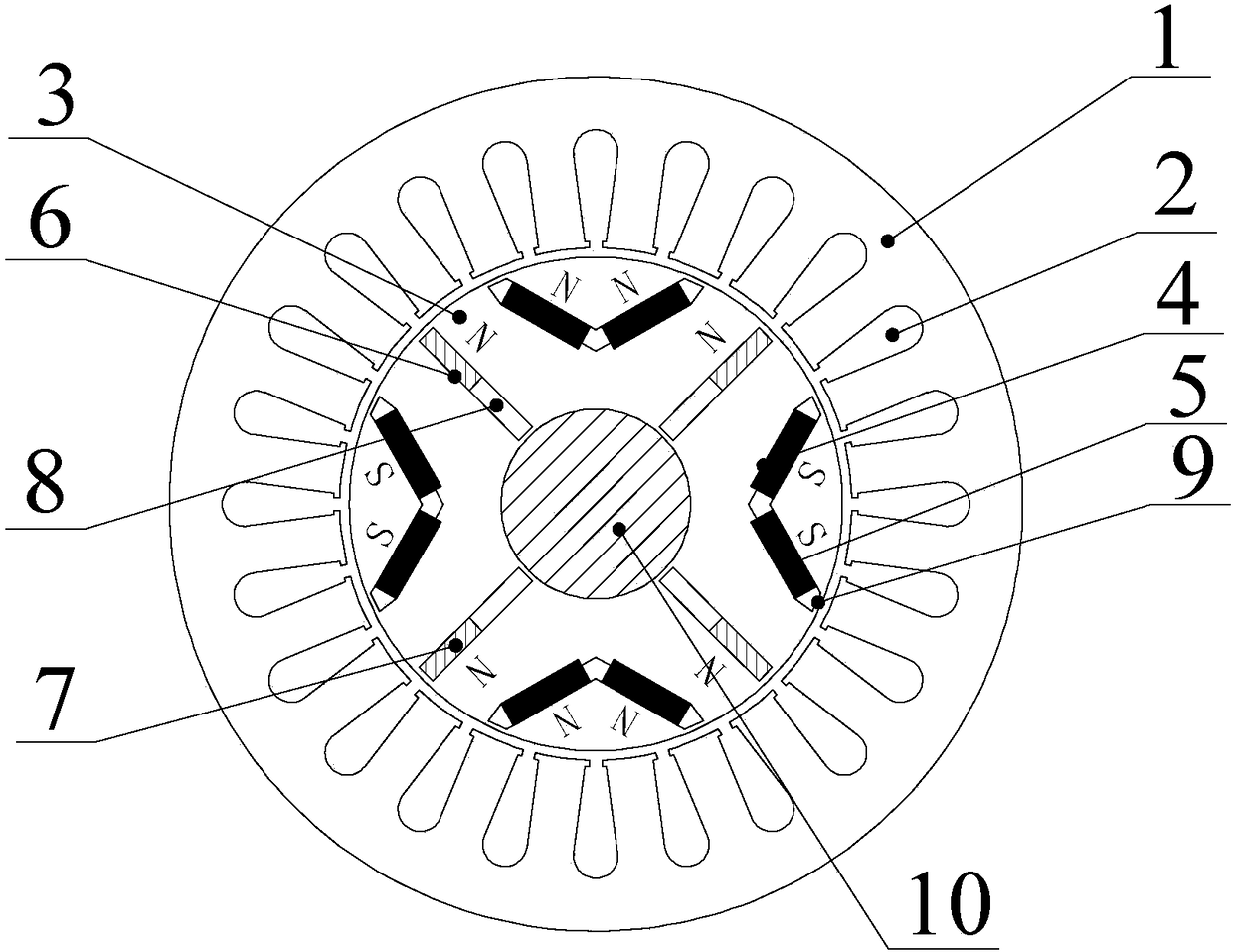
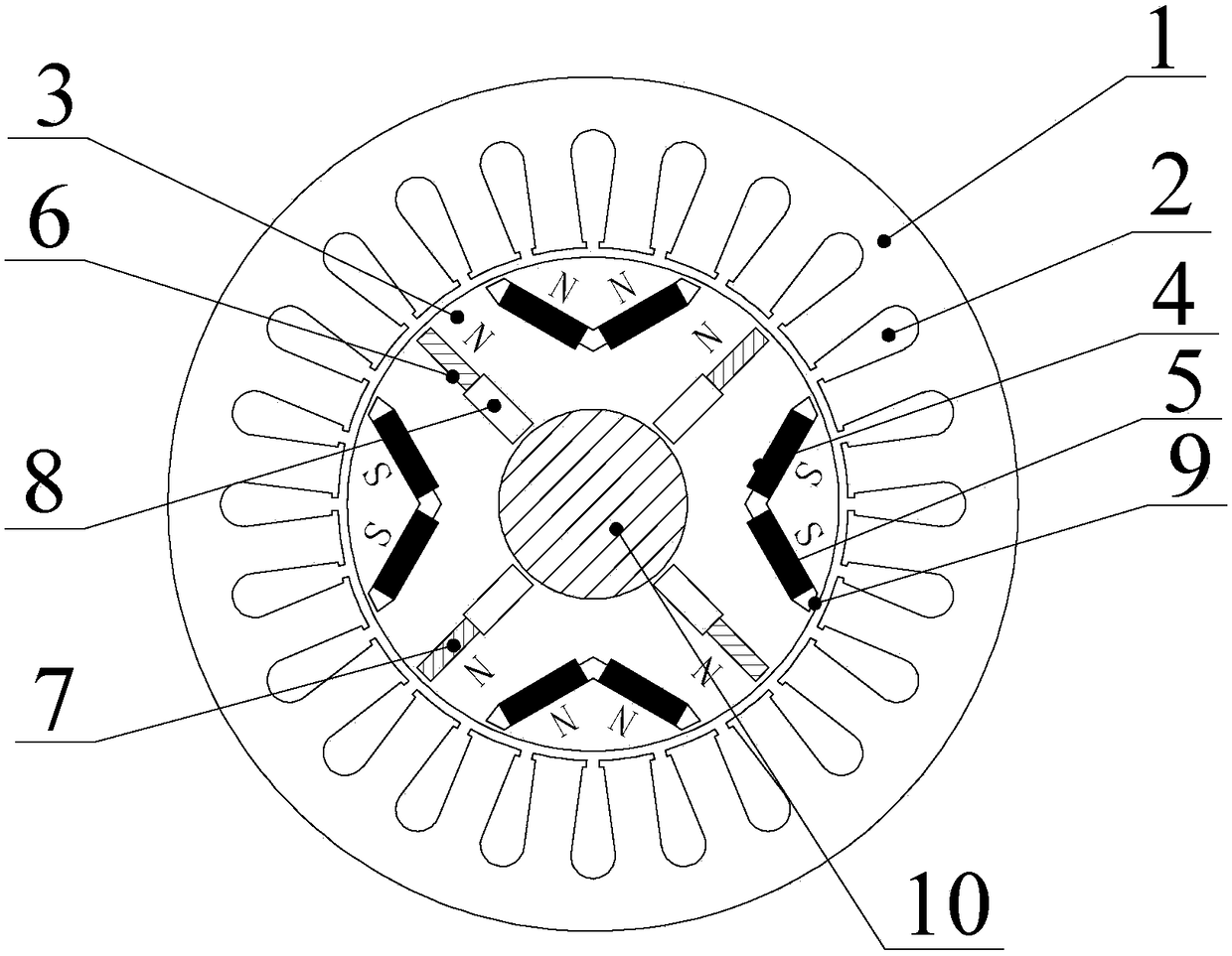
[0013] Specific implementation mode one: the following combination Figure 1 ~ Figure 4 Describe this embodiment, the semi-serial hybrid permanent magnet adjustable flux motor with passive magnetic barriers described in this embodiment, including stator core 1, armature winding 2, rotor core 3 and rotating shaft 10; rotor core 3 is fixed On the rotating shaft 10 and located inside the stator core 1, the armature winding 2 is arranged on the stator core 1;

[0014] It also includes low coercive force permanent magnet slots 4, low coercive force permanent magnets 5, radial slots 6, high coercive force permanent magnets 7 and passive magnetic adjustment magnetic barriers 8, and the rotor cores 3 are alternately and evenly arranged in low coercive force along the circumferential direction. The coercivity permanent magnet slot 4 and the radial slot 6, the low coercivity permanent magnet slot 4 and the radial slot 6 run through the entire motor in the axial direction, and the low co...

specific Embodiment approach 2

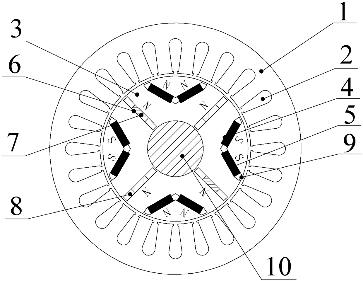
[0016] Specific embodiment two: the difference between this embodiment and embodiment one is that the low-coercivity permanent magnet groove 4 adopts a V-shaped groove or a straight groove, and when a V-shaped groove is adopted, the two straight grooves of the V-shaped groove A low-coercivity permanent magnet 5 is respectively set in each; when adopting the inline groove, a low-coercivity permanent magnet 5 is set in the low-coercivity permanent magnet groove 4; The radial groove 6 is an inline groove.

specific Embodiment approach 3

[0017] Specific embodiment three: the difference between this embodiment and embodiment two is that the magnetization direction of the low-coercivity permanent magnet 5 is perpendicular to the long side of the low-coercivity permanent magnet slot 4, and two adjacent low-coercivity The magnetization direction of coercive force permanent magnet 5 is opposite; The magnetization directions are opposite, and under the same magnetic pole, the low-coercivity permanent magnet 5 and the high-coercivity permanent magnet 7 are both N poles or S poles.

[0018] see Figure 1 ~ Figure 3 , the magnetization direction of the low-coercivity permanent magnet 5 is perpendicular to the long side of the low-coercivity permanent magnet slot 4, and has a certain angle with the radial direction, and the size of the angle is the same as that of the two straight grooves in the V-shaped groove. The angles assumed are related.

[0019] see Figure 4 , the magnetization direction of the low-coercivity...


PUM


Abstract

The invention discloses a mid-series type hybrid permanent-magnet adjustable flux motor having passive adjustable flux magnetic barriers, and belongs to the field of permanent-magnet motors, and solves the problem that advantages of serial and parallel hybrid permanent-magnet adjustable flux motors cannot be combined. The mid-series type hybrid permanent-magnet adjustable flux motor comprises a stator iron core, an armature winding, a rotor iron core and a rotating shaft; the rotor iron core is fixed on the rotating shaft, and is positioned inside the stator iron core; the armature winding isarranged on the stator iron core; the mid-series type hybrid permanent-magnet adjustable flux motor further comprises low-coercivity permanent-magnet slots, low-coercivity permanent magnets, radial slots, high-coercivity permanent magnets and the passive adjustable flux magnetic barriers; the low-coercivity permanent-magnet slots and the radial slots are distributed on the rotor iron core alternately and uniformly along a circumferential direction; the low-coercivity permanent-magnet slots and the radial slots are penetrated through the whole motor along an axial direction; the low-coercivitypermanent magnets are installed in the low-coercivity permanent-magnet slots; and the high-coercivity permanent magnets and the passive adjustable flux magnetic barriers are jointly installed in the radial slots.

Description

technical field [0001] The invention relates to a semi-serial hybrid permanent magnet adjustable magnetic flux motor rotor structure with a passive magnetic barrier and belongs to the field of permanent magnet motors. Background technique [0002] The adjustable flux permanent magnet motor adjusts the magnetization level of the low-coercivity permanent magnet online by applying an instantaneous direct-axis demagnetization pulse current in the armature winding, reducing the air gap flux density of the motor, thereby expanding the speed regulation range of the motor, and It can ensure high efficiency when the motor runs at a wide speed. The adjustable flux motor using a single low coercivity permanent magnet has low power density, and a hybrid permanent magnet adjustable flux motor using both low coercivity permanent magnets and high coercivity permanent magnets has emerged as the times require. The arrangement of the two permanent magnets of this type of motor can be divided...

Claims


Application Information

Patent Timeline
Patent Type & Authority Applications(China)
IPC IPC(8): H02K21/02H02K1/27
CPCH02K1/2773H02K21/028H02K2213/09
Inventor 郑萍张书宽王明峤乔光远刘法亮
Owner 黑龙江省工研院资产经营管理有限公司
Why Eureka
Try Eureka