Extruding universal formwork

A common mold base and mold base technology, applied in the field of extrusion, can solve the problems of affecting production efficiency, cumbersome mold base replacement process, and low versatility of mold bases

Pending Publication Date: 2018-06-05
厦门市克成五金制品有限公司
View PDF0 Cites 1 Cited by
  • Summary
  • Abstract
  • Description
  • Claims
  • Application Information

AI Technical Summary

Problems solved by technology

Therefore, the versatility of the formwork is not high, and the replacement process of the formwork is also very cumbersome, which affects the production efficiency

Method used


Image

  • Extruding universal formwork
  • Extruding universal formwork
  • Extruding universal formwork

Examples


Embodiment 1

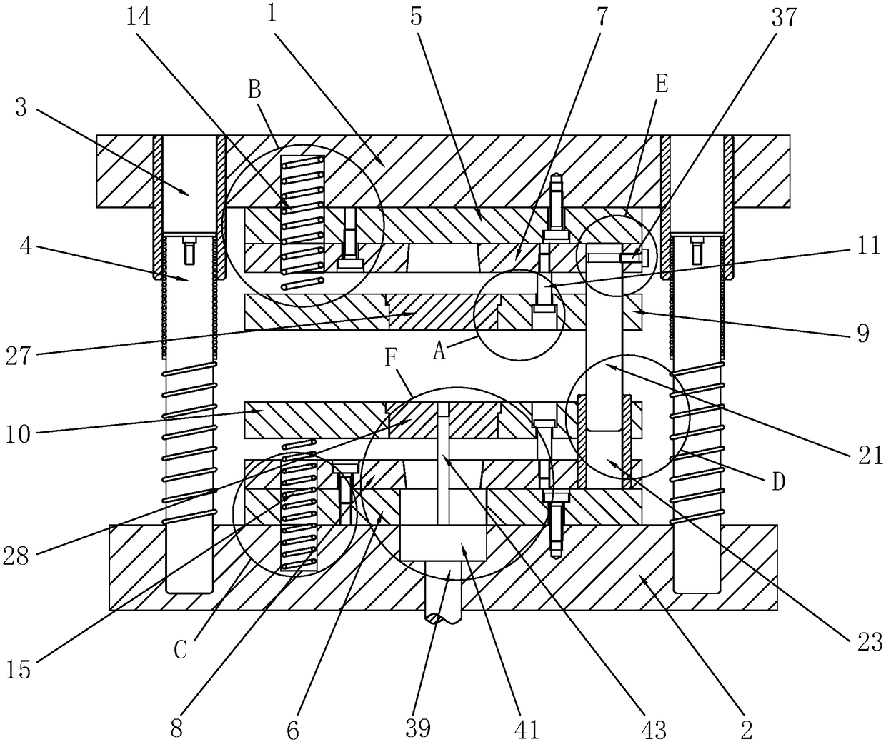
[0043] Embodiment 1: A kind of extruded universal formwork, such as figure 1 As shown, it includes an upper mold base 1 and a lower mold base 2; a guide sleeve 3 is plugged into the upper mold base 1 in the form of an interference fit, and a sliding end is inserted into the lower mold base 2 in the form of an interference fit The guide post 4 inserted into the guide sleeve 3; among them, the guide post 4 is preferably a ball guide post, which has the characteristics of high precision and long service life, and is suitable for precision molds with high precision and long life and punching of thin materials mold. Upper die base 1 is connected with upper backing plate 5 by screws, lower die base 2 is connected with lower backing plate 6 by screws; upper backing plate 5 is connected with upper stress backing plate 7 by screws, and lower backing plate 6 is connected with lower stress by screws Backing plate 8.

[0044] combine image 3 and Figure 4 , the extruded universal for...

Embodiment 2

[0050] Embodiment 2: as Figure 9 and Figure 10 As shown, the difference from Embodiment 1 is that the upper stripping plate 9, the lower stripping plate 10, the upper template 16 and the lower template 17 are provided with pin holes 20 for installing positioning pins 19. After the spring is unloaded, the upper backing plate 5, the upper stress backing plate 7 and the upper stripping plate 9 are rigidly connected by screws, and the upper template 16 is mounted on the upper stripping plate 9; the lower template 17 is installed on the lower stripping plate 10 superior. The second spring acts as a buffer when closing the mold to prevent the extruded part from being torn due to excessive impact.

Embodiment 3

[0051] Example 3: Binding Figure 10 and Figure 11 , the difference from Example 1 is that pin holes 20 are provided on the upper stripping plate 9, the lower stripping plate 10, the upper template 16 and the lower template 17, and the pin holes 20 are inserted with positioning pins 19 in the form of transition fit. . After the spring 2 is removed, the lower backing plate 6, the lower stress backing plate 8 and the lower stripping plate 10 are rigidly connected by screws, and the upper template 16 is mounted on the upper stripping plate 9; the lower template 17 is installed on the lower stripping plate 10 superior. When the spring is closed, it acts as a buffer to prevent the extruded part from being torn due to excessive impact.


PUM


Abstract

The invention discloses an extruding universal formwork which comprises an upper mould base and a lower mould base, wherein the upper mould base is connected with an upper cushion plate, the lower mould base is connected with a lower cushion plate, the upper cushion plate is connected with an upper stress cushion plate, and the lower cushion plate is connected with a lower stress cushion plate. The extruding universal formwork further comprises an upper releasing plate and a lower releasing plate, wherein the upper releasing plate is connected with the upper stress cushion plate, the lower releasing plate is connected with a lower stress cushion plate, a first elastic part is in butt joint between the upper mould base and the upper releasing plate, a second elastic part is in butt joint between the lower mould base and the lower releasing plate, and the upper releasing plate and the lower releasing plate can respectively abut against the upper stress cushion plate and the lower stresscushion plate in mould closing to ensure stable pressure; in mould opening, the first elastic part and the second elastic part respectively push the upper releasing plate and the lower releasing plateto break away from the upper stress cushion plate and the lower stress cushion plate; the upper releasing plate and the lower releasing plate can serve as mould plates to be used, and the upper releasing plate and the lower releasing plate can be loaded on an upper mould and a lower mould through threaded holes to be used as the mould plates; when the sizes of extruding parts are smaller, the upper mould plate and the lower mould plate can be loaded on the upper releasing plate and the lower releasing plate to perform extruding operation, or the upper releasing plate and the lower releasing plate are disassembled, and the upper mould plate and the lower mould plate are respectively arranged on the upper stress cushion plate and the lower stress cushion plate; thus, high universality is achieved.

Description

technical field [0001] The invention relates to the technical field of extrusion, more specifically, it relates to an extrusion universal mold base. Background technique [0002] The mold base is the support of the mold. It is the part that combines and fixes the various parts of the mold according to certain rules and positions, and enables the mold to be installed on the press to work. composition. Mold bases are inseparable from molds, and are widely used in the manufacturing and molding of plastic and metal products. [0003] Taking metal extrusion processing as an example, after years of development, the extrusion mold base production industry has become quite mature. Mold manufacturers can not only purchase customized mold bases according to individual mold needs, but also choose standardized mold base products. Standard formwork bases are available in a variety of styles, providing moldmakers with greater flexibility. In the prior art, the size of the extrusion di...

Claims


Application Information

Patent Timeline
IPC IPC(8): B21D37/12
CPCB21D37/12Y02P70/10
Inventor 李建波陈志强
Owner 厦门市克成五金制品有限公司
Why Eureka
Try Eureka