Piezoelectric stack-based vibration reduction ring device

A piezoelectric stacking, vibration-damping ring technology, applied in springs/shock absorbers, vibration suppression adjustment, rotational vibration suppression, etc. problems, to avoid tangential stress and torque, the equipment is simple and prominent, and the system vibration is reduced

Active Publication Date: 2018-06-05
NANJING UNIV OF AERONAUTICS & ASTRONAUTICS
View PDF7 Cites 12 Cited by
  • Summary
  • Abstract
  • Description
  • Claims
  • Application Information

AI Technical Summary

Problems solved by technology

[0003] However, the disadvantages of the squeeze film damper are: due to the high nonlinearity of the oil film stiffness, the squeeze film damper may lock up, bistable and uncoordinated precession during the working process, and the transmission system vibrates too much and even produces fatigue and crash
Moreover, drilling holes at the support will affect the strength and rigidity of the structure, so although it has the effect of damping vibration, it may make the structure unable to perform its normal functions and functions.
Second, the piezoelectric stack can withstand large stresses in the polarization direction, but cannot withstand excessive shear forces and torques
Obviously, in this environment, the reliability and service life of the piezoelectric stack are difficult to guarantee
Third, installing the piezo stack in this way does not guarantee interchangeability and standardization of parts
There are only four piezoelectric stacks distributed around the drive shaft, so it is difficult to produce a uniform vibration damping effect; and the vibration damping measures need to be installed in the box, which limits its use
Piezoelectric stacks break easily when subjected to shear and torque
Therefore, in the case of high-speed rotation of the rotor system, the environmental adaptability of the device is poor and the service life is short
Moreover, the device needs to bury the piezoelectric stack in the chassis, which is not easy to install and process for general engineering structures

Method used


Image

  • Piezoelectric stack-based vibration reduction ring device
  • Piezoelectric stack-based vibration reduction ring device
  • Piezoelectric stack-based vibration reduction ring device

Examples


Embodiment Construction

[0031] The present invention will be further described below in conjunction with embodiment. The following descriptions are only some, not all, embodiments of the present invention. Based on the embodiments of the present invention, all other embodiments obtained by persons of ordinary skill in the art without creative efforts fall within the protection scope of the present invention.

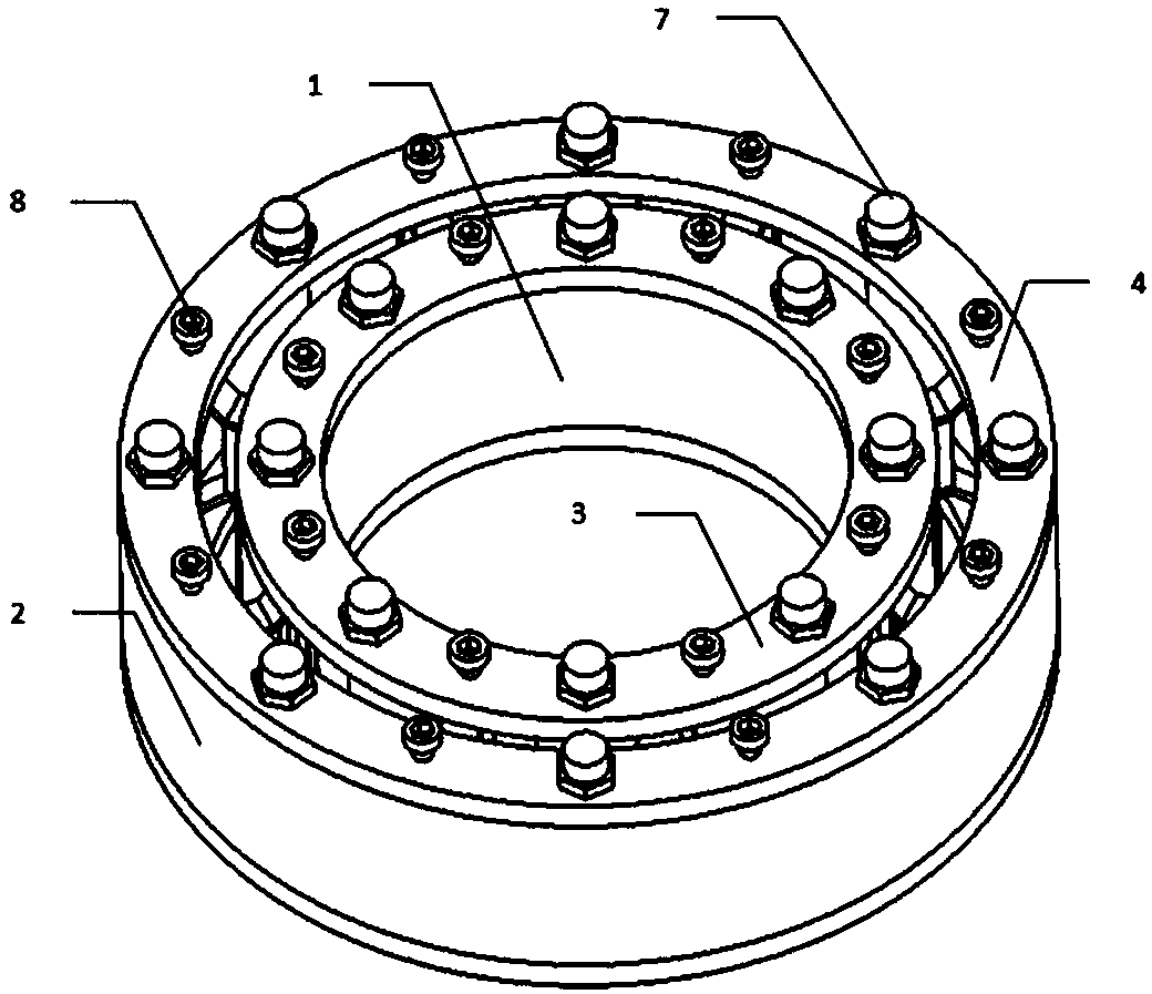
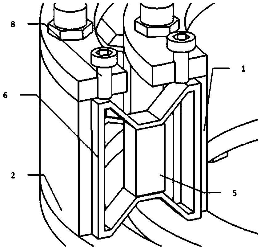
[0032] As shown in 2~10, the vibration damping ring device mainly includes an inner ring 1, an outer ring 2, an inner ring end cover 3, an outer ring end cover 4, a piezoelectric stack 5, and a butterfly connector 6. The butterfly connector Adhere to the upper and lower ends of the piezoelectric stack 5 respectively, align the grooves of the inner ring 1 and the outer ring 2 respectively, insert the butterfly connector 6 into the grooves between the inner ring 1 and the outer ring 2, pay attention During installation, ensure that the axes of the inner ring 1 and the outer ring 2 coincide.

[...


PUM


Abstract

The invention discloses a piezoelectric stack-based vibration reduction ring device, and belongs to the field of design for vibration reduction devices. The vibration reduction ring device comprises an inner ring, an outer ring, an inner ring end cover, an outer ring end cover, piezoelectric stacks and butterfly-shaped connection elements, wherein one piezoelectric stack is connected to the longitudinal symmetry axis of each butterfly-shaped connection element; the butterfly-shaped connection elements are uniformly distributed in aligned grooves between the inner ring and the outer ring; and the inner ring end cover and the outer ring end cover are further arranged at the upper ends of the inner ring and the outer ring separately. According to the novel vibration reduction ring design disclosed by the invention, the vibration reduction ring is capable of effectively reducing vibration transferred to supporting by a transmission system through a shaft and a bearing by virtue of a piezoelectric shunt damping technology, and capable of effectively preventing the piezoelectric stacks from bearing tangential stress and torque, thereby prolonging the service lives of the piezoelectric stacks.

Description

technical field [0001] The invention belongs to the design field of vibration damping devices, and specifically refers to a vibration damping ring device based on piezoelectric stacking. Background technique [0002] Traditional damping devices acting on bearings and housings include squeeze film dampers and the like. Squeeze oil film dampers are divided into squeeze oil film dampers with centering elastic support and without centering elastic support according to whether the journal center and bearing center are concentric when the rotor is not rotating. For example, in the research by Zhang Jiazhong and other scholars, a squeeze oil film damper with elastic support is provided (Zhang Jiazhong, Zheng Tiesheng, Liu Shixue, etc. Stability and analysis of squeeze oil film damper-sliding bearing-rigid transmission system Fork behavior. Acta Applied Mechanics, 1996,13(4):35~40). The Squeeze Oil Film Damper absorbs the vibration energy into heat energy and takes it away by the ...

Claims


Application Information

Patent Timeline
Patent Type & Authority Applications(China)
IPC IPC(8): F16F15/12F16F15/16F16F15/167F16F15/18
Inventor 何欢何晋丞谭星
Owner NANJING UNIV OF AERONAUTICS & ASTRONAUTICS
Why Eureka
Try Eureka