Dual-electromagnetic relay

A relay, dual electromagnetic technology, applied in the direction of electromagnetic relays, electromagnetic relay details, relays, etc., can solve problems such as too large or too small pull-in strength

Inactive Publication Date: 2018-06-05
王波
View PDF0 Cites 1 Cited by
  • Summary
  • Abstract
  • Description
  • Claims
  • Application Information

AI Technical Summary

Problems solved by technology

[0004] The purpose of the present invention is to solve the above-mentioned problems, provide a method that can quickly realize the attraction and separation of contacts, and at the same time accurately control the power supply circuit of the electromagnet, so as to indirectly control the strength of the generated magnetism and avoid the occurrence of contacts. Double electromagnetic relay for the case where the pull-in strength is too large or too small

Method used


Image

  • Dual-electromagnetic relay

Examples


Embodiment 1

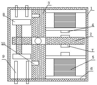
[0023] like figure 1 , a double electromagnetic relay of the present invention includes a casing 1, a fixing device, an electromagnetic assembly and a contact assembly; the fixing device includes a pole 2 and a support 3, and the support 3 is vertically fixed in the casing 1, and The rod 2 is horizontally arranged in the shell 1, and is fixed with the support 3 by bolts; the electromagnetic assembly includes the iron core 4, the coil 5, the coil frame 6, and the energized circuit on the coil 5; the coil frame 6 is fixed to the shell Between 1 and the support 3, an iron core 4 wound with a coil 5 is arranged on it; the contact assembly includes an armature 7 and a moving contact 8; the armature 7 is arranged on the upper surface and the lower surface of one end of the pole; The moving contact 8 is fixed on the other end of the pole; the contact assembly also includes a lead-out end 9 corresponding to the moving contact 8 and a permanent magnet 10 arranged in the support.

[0...

Embodiment 2

[0027] Compared with Embodiment 1, in this embodiment, electromagnetic assembly 1 and electromagnetic assembly 2 are respectively arranged above and below the pole 2, and contact assembly 1 and contact assembly 2 are respectively arranged between the pole 2 and the support 3. ; The setting of the two sets of contact components can control two associated working circuits, and the setting of the two sets of electromagnetic components can cooperate to control the pull-in and separation of the contacts.

Embodiment 3

[0029] Compared with Embodiment 1 and Embodiment 2, in this embodiment, when the electromagnetic assembly and the contact assembly are respectively arranged on the same side of the pole 2, the working circuit is disconnected when the electromagnetic is energized, and the working circuit is disconnected when it is separated. connected.


PUM


Abstract

The invention discloses a dual-electromagnetic relay which is characterized in that the dual-electromagnetic relay comprises a shell, a fixed device, electromagnetic components and contact components,the fixed device comprises a support rod and a support seat, the support seat is vertically fixed in the shell, the support rod is horizontally arranged and is fixed with a support seat by bolts, each of the electromagnetic components comprises an iron core, a coil, a coil frame and an energization circuit on the coil, the coil frame is fixed between the shell and the support seat, the iron corewhich is wrapped in the coil is arranged on the coil frame, each of the contact components comprises an armature and a moving contact, the armatures are arranged on an upper surface and a lower surface of one end of the support rod, the moving contacts are fixed to the other end of the support rod, and the contact components also comprise leading-out ends corresponding to the moving contacts and permanent magnets arranged in the supporting seat. According to the dual-electromagnetic relay, the attraction and separation of the contacts can be quickly achieved, and at the same time, the attraction and release of the contacts are effectively controlled through detecting the distances of the contacts.

Description

technical field [0001] The invention relates to the field of relays, in particular to a double electromagnetic relay. Background technique [0002] Electromagnetic relays are generally composed of electromagnets, armatures, spring sheets, contacts, etc., and their working circuits are composed of low-voltage / low-current control circuits and high-voltage / high-current working circuits. Electromagnetic relays can also realize remote control and automatic control. As long as a certain voltage is applied to both ends of the coil, a certain current will flow through the coil, thereby generating an electromagnetic effect. The moving contact and the static contact (normally open contact) are sucked together. When the coil is powered off, the electromagnetic attraction will also disappear, and the armature will return to its original position under the reaction force of the spring, so that the moving contact and the original static contact (normally closed contact) will be released...

Claims


Application Information

Patent Timeline
Patent Type & Authority Applications(China)
IPC IPC(8): H01H50/16H01H50/44H01H50/54
CPCH01H50/16H01H50/44H01H50/54
Inventor 王波
Owner 王波
Why Eureka
Try Eureka