
Signal synchronization control method and apparatus

A synchronous control and signal technology, applied in pulse shaping and other directions, can solve the problems of MCU large electromagnetic interference, increased internal current power consumption, system instability, etc., to reduce electromagnetic interference, improve stability, and eliminate resonance phenomenon.

Active Publication Date: 2018-06-05
BYD SEMICON CO LTD
View PDF5 Cites 1 Cited by
  • Summary
  • Abstract
  • Description
  • Claims
  • Application Information

AI Technical Summary

Problems solved by technology

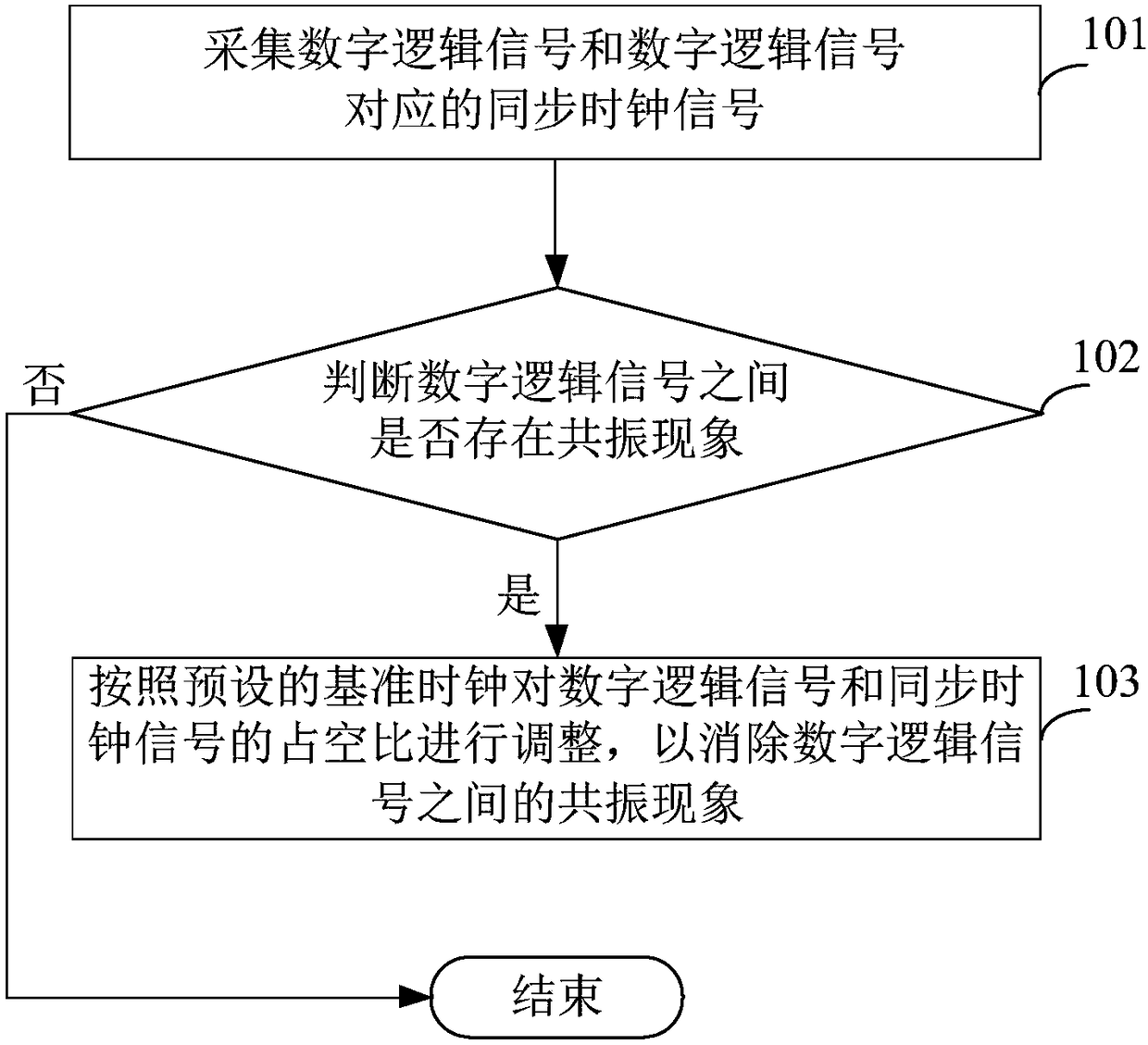
When the frequency of the synchronous clock is extremely high, it often occurs that a large number of digital logic signals jump to the rising edge of the corresponding clock control signal at the same time, and the probability of jumping to the falling edge at the same time also increases significantly, and the above digital logic signals simultaneously jump to The phenomenon of falling edge may cause "resonance" phenomenon
In practical applications, when the above-mentioned "resonance" phenomenon occurs, the power consumption of the internal current of the MCU will increase rapidly. When the current changes instantaneously at a high frequency, it may cause large electromagnetic interference to the entire MCU, resulting in system instability.

Method used


Image

  • Signal synchronization control method and apparatus
  • Signal synchronization control method and apparatus
  • Signal synchronization control method and apparatus

Examples


Embodiment Construction

[0025] Embodiments of the present invention are described in detail below, examples of which are shown in the drawings, wherein the same or similar reference numerals denote the same or similar modules or modules having the same or similar functions throughout. The embodiments described below by referring to the figures are exemplary only for explaining the present invention and should not be construed as limiting the present invention. On the contrary, the embodiments of the present invention include all changes, modifications and equivalents coming within the spirit and scope of the appended claims.

[0026] In addition, the terms "first" and "second" are used for descriptive purposes only, and cannot be interpreted as indicating or implying relative importance or implicitly specifying the quantity of indicated technical features. Thus, a feature defined as "first" and "second" may explicitly or implicitly include one or more of these features. In the description of the pre...


PUM


Abstract

The invention provides a signal synchronization control method and apparatus. The signal synchronization control method comprises the following steps: collecting digital logic signals and synchronousclock signals corresponding to the digital logic signals, judging whether the digital logic signals have a resonance phenomenon, and when the digital logic signals have the resonance phenomenon, adjusting the duty ratios of the digital logic signals and the synchronous clock signals according to a preset reference clock to eliminate the resonance phenomenon. By changing the duty ratios of the digital logic signals and the synchronous clock signals, the resonance phenomenon between the digital logic signals is eliminated, the number of the digital logic signals that jump to the falling edge under the triggering on the rising edge of the respective synchronous clock signals can be reduced, and the "resonance" phenomenon is reduced, thereby reducing the electromagnetic interference to an MCUand improving the stability of the system.

Description

technical field [0001] The invention relates to the technical field of digital signal processing, in particular to a signal synchronization control method and device. Background technique [0002] The synchronization design of each digital logic signal is the most important content in the design of the digital logic control of the current micro control unit (Micro Controller Unit, referred to as MCU). In general, each digital logic signal can be controlled synchronously through a clock domain. Specifically, a unique fixed frequency is set for the clock domain, and all digital logic signals jump based on the rising edge or falling edge of the clock domain. For example, set on a rising edge, or release on a falling edge. [0003] In an MCU with complex digital logic control, a large number of digital logic signals are often required. When the frequency of the synchronous clock is extremely high, it often occurs that a large number of digital logic signals jump to the rising...

Claims


Application Information

Patent Timeline
Patent Type & Authority Applications(China)
IPC IPC(8): H03K5/04
CPCH03K5/04
Inventor 周博李奇峰杨云
Owner BYD SEMICON CO LTD
Learn More