Exhaust gas pollution treating device

A technology for pollution control and exhaust gas, which is applied in the direction of cleaning hollow objects, cleaning methods and appliances, engines, etc., can solve the problems of inability to clean exhaust gas pipelines and high-efficiency conversion of residual pressure, and achieve resource utilization of exhaust gas, energy conversion, and use convenient effect

Inactive Publication Date: 2018-06-08
毛利英
View PDF4 Cites 0 Cited by
  • Summary
  • Abstract
  • Description
  • Claims
  • Application Information

AI Technical Summary

Problems solved by technology

[0002] In industrial smelting and production, more industrial waste gas with heat is often produced. In order to realize the utilization of waste gas resources, waste gas conversion devices are generally used to convert and utilize the waste heat and pressure in these waste gases. However, the traditional The exhaust gas conversion device can not better realize the cleaning of the exhaust gas pipeline and the efficient conversion of the residual pressure. This device solves this problem to a large extent

Method used


Image

  • Exhaust gas pollution treating device
  • Exhaust gas pollution treating device
  • Exhaust gas pollution treating device

Examples


Embodiment Construction

[0020] All features disclosed in this specification, or steps in all methods or processes disclosed, may be combined in any manner, except for mutually exclusive features and / or steps.

[0021] Any feature disclosed in this specification (including any appended claims, abstract and drawings), unless expressly stated otherwise, may be replaced by alternative features which are equivalent or serve a similar purpose. That is, unless expressly stated otherwise, each feature is one example only of a series of equivalent or similar features.

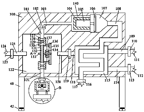
[0022] Such as Figure 1-4As shown, a waste gas pollution treatment device of the present invention includes a chassis A100, four corners of the bottom of the chassis A100 are provided with support columns 40, and each of the support columns 40 corners is provided with threaded holes 41 at the bottom. , the screw thread in the threaded hole 41 is fitted with a screw angle 42, through which the screw angle 42 can be adjusted when the ground is...


PUM


Abstract

The invention discloses an exhaust gas pollution treating device which comprises a chassis A, wherein supporting columns are arranged on four corners of the bottom of the chassis a; a threaded hole isformed in the bottom of the angle of each supporting column; a screwing screw angle is mounted in the threaded hole in a threaded matching manner; a rotary cavity is formed in the chassis A; a ventilating pipe A extending leftward to the outer side is communicated with the left end wall of the rotary cavity; an electric control valve A is communicated with the left end surface of the ventilatingpipe A; a ventilating pipe B is communicated with the left end surface of the electric control valve A; a ventilating pipe C is communicated with the right end wall of the rotary cavity; a solution cavity located in the chassis is formed in the right side of the ventilating pipe; an electric control valve B is communicated with the right end surface of the ventilating pipe C; a ventilating pipe Dcommunicating to the solution cavity is communicated with the right end surface of the electric control valve; a ventilating pipe E extending rightward to the outer side is communicated with the rightend wall of the solution cavity; and an electric control valve is communicated with the right end surface of the ventilating pipe E.

Description

technical field [0001] The invention relates to the field of exhaust gas conversion treatment, in particular to an exhaust gas pollution treatment device. Background technique [0002] In industrial smelting and production, more industrial waste gas with heat is often produced. In order to realize the utilization of waste gas resources, waste gas conversion devices are generally used to convert and utilize the waste heat and pressure in these waste gases. However, the traditional The exhaust gas conversion device can not better realize the cleaning of the exhaust gas pipeline and the efficient conversion of the residual pressure. This device largely solves this problem. Contents of the invention [0003] The object of the present invention is to provide an exhaust gas pollution control device that can overcome the above-mentioned defects of the prior art. [0004] According to the present invention, a waste gas pollution treatment device of the present invention comprises...

Claims


Application Information

Patent Timeline
Patent Type & Authority Applications(China)
IPC IPC(8): B01D53/00F03D9/25B08B9/032
CPCB01D53/00B08B9/0321F03D9/25Y02E10/72
Inventor 毛利英
Owner 毛利英
Why Eureka
Try Eureka