A hydrolysis ammonia supply and denitrification system for power plants and its control method

A technology for ammonia supply and denitrification, which is applied in separation methods, chemical instruments and methods, gas treatment, etc., can solve the problems of fluctuation, unstable ammonia gas fluctuation, improper control methods, etc., and achieves low power consumption, high desulfurization rate, and energy saving. effect of investment

Inactive Publication Date: 2019-08-02
DATANG LUOYANG SHOUYANGSHAN POWER PLANT
View PDF6 Cites 0 Cited by
  • Summary
  • Abstract
  • Description
  • Claims
  • Application Information

AI Technical Summary

Problems solved by technology

[0006] The purpose of the present invention is to provide a hydrolysis ammonia supply denitrification system for power plants to solve the problem that fluctuations in the process of ammonia gas preparation by hydrolysis caused by improper control methods in the existing denitrification technology lead to fluctuations and instability of ammonia gas supply in the later stage and its control method

Method used


Image

  • A hydrolysis ammonia supply and denitrification system for power plants and its control method
  • A hydrolysis ammonia supply and denitrification system for power plants and its control method

Examples


Embodiment Construction

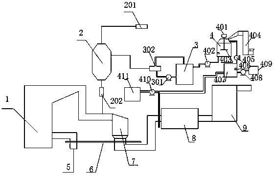
[0037] As shown in the figure, the specific implementation method is as follows:

[0038]A hydrolysis ammonia denitrification system used in a power plant, comprising an SCR reactor 7 and a dust collector 8 serially connected in series on the gas outlet pipeline of a boiler 1, and an air preheater is installed on the pipeline connected between the SCR reactor 7 and the dust collector 8. Heater 6, the pipeline of the air supply inlet 5 of the boiler 1 is connected with the air preheater 6 so as to preheat the air entering the boiler 1 by using the waste heat of the exhaust gas of the boiler 1, and also includes a controller for controlling the automatic operation of the whole system, The ammonia injection grid in the SCR reactor 7 is connected to the hydrolyzer 2, and the pipeline connected to the ammonia injection grid and the hydrolyzer 2 is provided with an adjustment module 202 for controlling the amount of ammonia gas fed into the hydrolyzer. The adjustment module 202 It i...


PUM


Abstract

The invention discloses a hydrolytic ammonia supply and denitration system for a power plant. The hydrolytic ammonia supply and denitration system comprises an SCR reactor and a dust remover which aresequentially connected in series to an air outlet pipeline of a boiler; an ammonia spraying grating in the SCR reactor is connected with a hydrolyzer; an inlet of the hydrolyzer is connected with a urea solution storage tank by a first high-flow pump; the urea solution storage tank is connected with a urea dissolution tank by a second high-flow pump; the urea dissolution tank is connected with awater storage tank by a third high-flow pump; the urea dissolution tank is internally provided with a first temperature sensor; the water storage tank is internally provided with a second temperaturesensor; and the temperature in the urea dissolution tank is controlled to be constant as 20 DEG C by a controller according to the temperatures measured by the first temperature sensor and the secondtemperature sensor. Due to the mutual matching of the first temperature sensor and the second temperature sensor, the stability of urea dissolution temperature is guaranteed, so that urea can be randomly and rapidly dissolved, the solution concentration is guaranteed, it is convenient to realize automatic control and dynamic regulation, and meanwhile, the problem that low dissolution efficiency caused by heat absorption resulted from urea dissolution affects the solubility of the solution to result in later ammonia control inaccuracy is also avoided.

Description

technical field [0001] The invention relates to a power plant denitrification technology, in particular to a hydrolysis ammonia supply denitrification system for a power plant and a control method thereof. Background technique [0002] After the denitrification system is transformed from pyrolysis reaction to hydrolysis and pyrolysis reaction, the operating conditions of the system have changed greatly, resulting in large fluctuations in the automatic adjustment of ammonia injection. The present invention can improve the automatic input rate of ammonia injection by modifying the control logic and improving optimization. Reduce ammonia injection system fluctuations. Because the national environmental protection department has put forward higher requirements for flue gas NOX emissions. In the process of SCR flue gas denitrification, the automatic optimization of ammonia injection is related to the operation cost, equipment safety, secondary pollution and even the risk of envi...

Claims


Application Information

Patent Timeline
Patent Type & Authority Patents(China)
IPC IPC(8): B01D53/86B01D53/90B01D53/56B01D53/50B01D53/78B01D53/75
CPCB01D53/502B01D53/504B01D53/75B01D53/8631B01D53/90B01D2258/0283
Inventor 张永智何欣杨超群王成武苏伟力李平谢文辉
Owner DATANG LUOYANG SHOUYANGSHAN POWER PLANT
Why Eureka
Try Eureka