
Automatic punching and placing machine

An automatic punching and placing technology, applied in metal processing and other directions, can solve the problems of increasing R&D and manufacturing costs, increasing product defect rate, increasing turnover cycle, etc., achieving the effect of ingenious design, lowering production costs, and reducing turnover process.

Pending Publication Date: 2018-06-08
CHANGZHOU GIAN TECH
View PDF0 Cites 3 Cited by
  • Summary
  • Abstract
  • Description
  • Claims
  • Application Information

AI Technical Summary

Problems solved by technology

[0002] At present, in the 3C industry, automatic punching and decoration are indispensable and important links in the entire process. However, since the two processes are separated in different workshops, the current common practice is to design and manufacture a single process in two different processes. The disadvantage of non-standard machines is that it increases various R&D and manufacturing costs, increases the turnover cycle, and increases the defective rate of products.

Method used


Image

  • Automatic punching and placing machine
  • Automatic punching and placing machine
  • Automatic punching and placing machine

Examples


Embodiment Construction

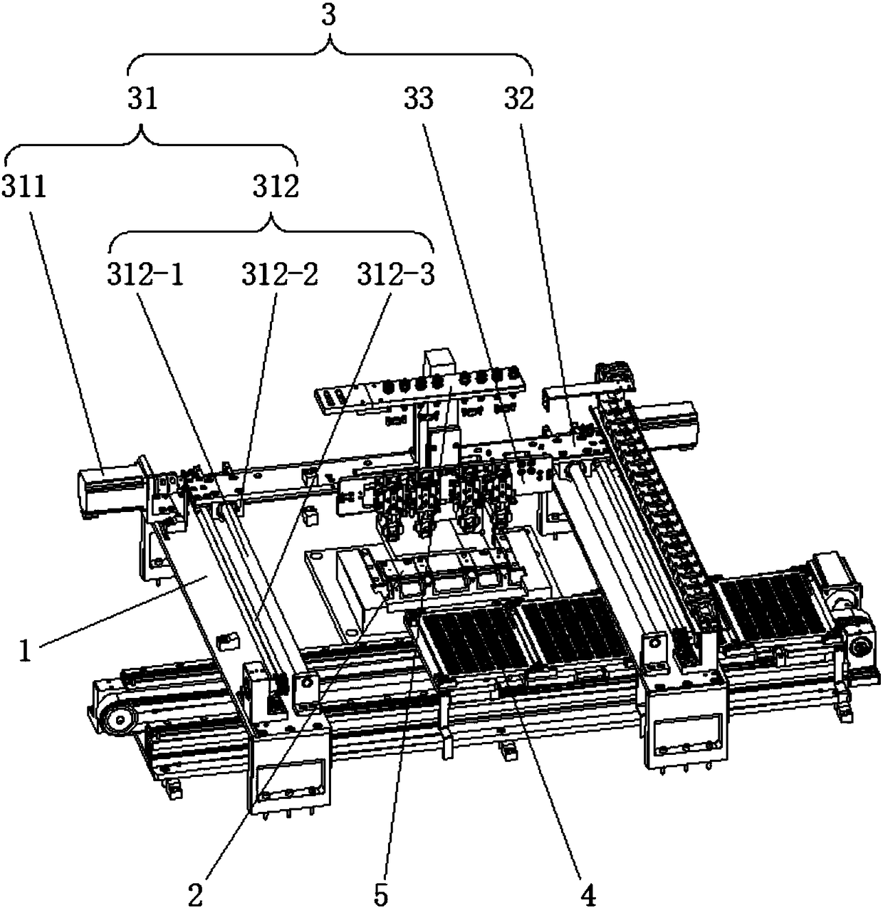
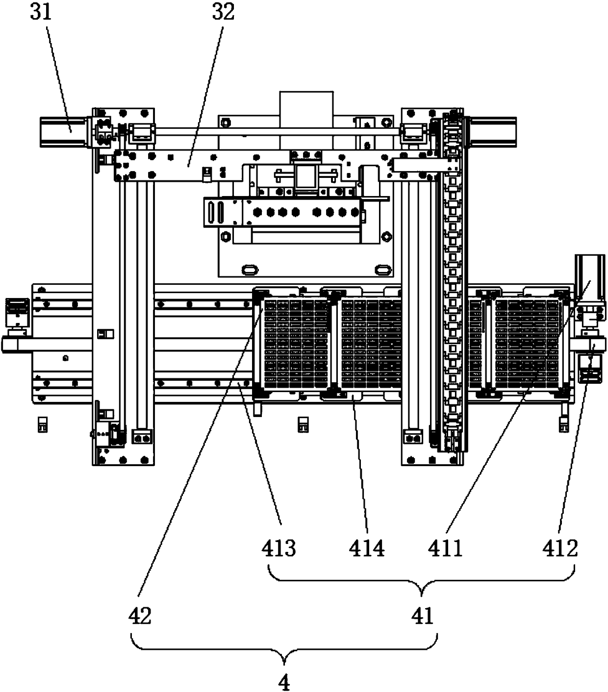
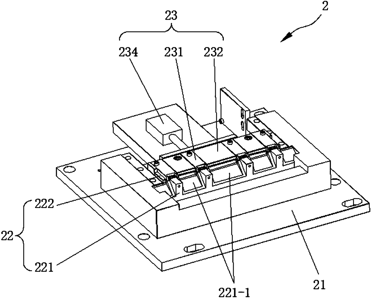
[0027] See Figure 1 to Figure 5 , the present invention has a frame 1; the frame 1 is provided with a punching mechanism 2, a transfer mechanism 3 and a pendulum mechanism 4; the punching mechanism 2 includes a substrate 21, and the substrate 21 is fixedly connected to the frame 1; The substrate 21 is provided with a clamping assembly 22 that can clamp the workpiece, and a punching assembly 23 that can punch the workpiece; the clamping assembly 22 is provided with a plurality of clamping positions; the punching The component 23 is provided with a punching head 231 corresponding to the clamping position one by one;

[0028] The transfer mechanism 3 includes a support frame 32 fixedly connected to the sliding device 31; the support frame 32 is provided with a plurality of clamping assemblies 33 corresponding to the clamping positions one by one and used for clamping the workpiece;

[0029] The pendulum mechanism 4 includes a plurality of pendulum plates 42 arranged on the tran...


PUM


Abstract

The invention relates to an automatic punching and placing machine. The automatic punching and placing machine comprises a machine frame; a punching mechanism, a transferring mechanism and a placing mechanism are arranged on the machine frame; the punching mechanism comprises a base plate, a clamping assembly capable of clamping workpieces and a punching assembly capable of punching the workpiecesare arranged on the base plate, a plurality of clamping positions are arranged on the clamping assembly, and punching heads corresponding to the clamping positions in a one-by-one mode are arranged on the punching assembly; the transferring mechanism comprises a supporting frame fixedly connected on a sliding device, and a plurality of holding assemblies corresponding to the clamping positions ina one-by-one mode are arranged on the supporting frame; the placing mechanism comprises a plurality of placing discs arranged on a transmission device, and the quantity of the placing discs is equalto the quantity of the clamping positions; a plurality of containing grooves for containing the workpieces are formed in the placing discs in a rectangular-array mode; the holding assemblies are driven by the sliding device to reciprocate between the clamping assembly and the placing discs. According to the automatic punching and placing machine, the punching working procedure and the placing working procedure are integrated, and product tracking can be achieved.

Description

technical field [0001] The invention relates to automatic equipment for 3C product manufacturing, in particular to an automatic punching and placing machine. Background technique [0002] At present, in the 3C industry, automatic punching and decoration are indispensable and important links in the entire process. However, since the two processes are separated in different workshops, the current common practice is to design and manufacture a single process in two different processes. The disadvantage of non-standard machines is that it increases various R&D and manufacturing costs, increases the turnover cycle, and at the same time increases the defective rate of products. Contents of the invention [0003] The object of the present invention is to provide an automatic punching and placing machine which combines the punching process and the placing process and has a high degree of automation. [0004] The technical solution for realizing the purpose of the present inventio...

Claims


Application Information

Patent Timeline
Patent Type & Authority Applications(China)
IPC IPC(8): B26F1/40B26D7/02B26D7/06B26D7/18B26D7/32
CPCB26D7/02B26D7/06B26D7/18B26D7/32B26F1/40
Inventor 孟江源王明喜
Owner CHANGZHOU GIAN TECH
Learn More