Swing type ignition signal generation device and rotating speed detection device
A technology for generating devices and ignition signals, applied in engine components, combustion engines, machines/engines, etc., can solve the problems of large space occupation, complex and troublesome detection system, and achieve the effect of reducing detection difficulty, compact structure and simple detection method.
- Summary
- Abstract
- Description
- Claims
- Application Information
AI Technical Summary
Problems solved by technology
Method used
Image

Examples
Embodiment 1
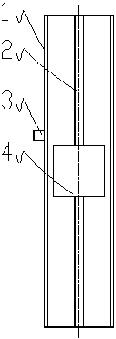
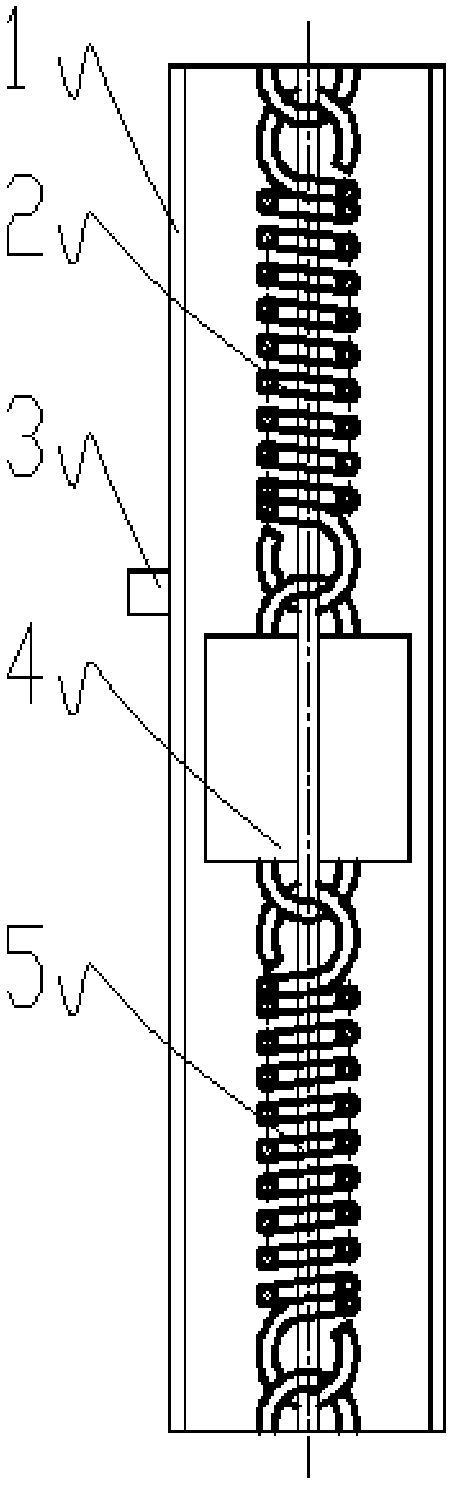
[0026] Such as figure 1 , A swing type ignition signal generating device, the swing type ignition signal generating device is installed on the shaft of the swing device of the swing engine, and includes a generating device housing 1 connected to the shaft 10 of the swing device. The pendulum core 4 and the elastic structure 2 in the device housing 1, and the generator housing 1 is preferably cylindrical or rectangular. At least one end of the pendulum core 4 is connected to the inner wall of the generator housing 1 through an elastic structure 2, and a position detection sensor 3 is installed on the outer side of the generator housing 1. The swing type ignition signal generating device also includes a guide rod 5, such as figure 2 Preferably, the elastic structure 2 may be a spring. Of course, the elastic structure 2 may be an elastic structure 2 made of rubber or other elastic materials. There are two elastic structures 2, the pendulum core 4 and the elastic structure 2 are b...
Embodiment 2
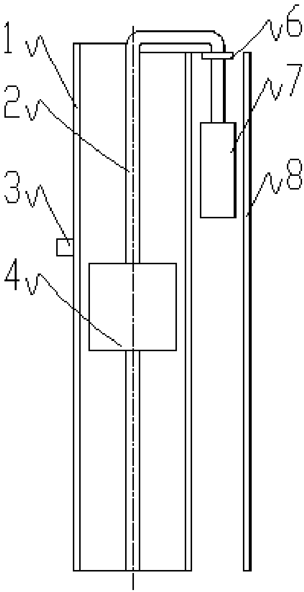
[0029] Such as image 3 The swing type ignition signal generating device is the same as the embodiment 1, but the outer side of the generating device housing 1 is also provided with a balance weight 7 and a balance weight placement plate 8 matched with the balance weight 7, and the balance weight The block 7 is connected to the elastic structure 2, and the elastic structure 2 is fixed to the end of the generator housing 1 by a limiting clip 6. Due to the action of the balance weight 7, it can be solved that the static position of the pendulum core 4 is affected by gravity. Specifically, when the swing type ignition signal generating device of the present invention is placed horizontally, the balance weight 7 is affected by gravity. It falls on the generator housing 1 or the counterweight placement plate 8; when the swing type ignition signal generator of the present invention is placed vertically, the balance counterweight 7 is offset by the gravity of the pendulum core 4, at th...
Embodiment 3
[0031] Such as Figure 4 When the swing type ignition signal generating device is used as a rotation speed detection device, it is the same as the embodiment 1, but the pendulum core 4 is provided with a gradient gray plate 9 on the side close to the position detection sensor 3, and the position The detection sensor 3 is an optical fiber sensor, and the position detection sensor 3 is within the range of the gradient gray plate 9 during the movement. Due to the different rotation speed of the swing device, the centrifugal force applied to the pendulum core 4 is also different. The balance position of centrifugal force and spring force is also different. In this way, when the gradient gray scale board 9 is in different positions, its corresponding gray levels are different, and the different rotation speeds of the pendulum core 4 can correspond to different positions of the gradient gray scale board 9. By detecting the intensity of the optical signal returned by the fiber optic se...
PUM
 Abstract
Description
Claims
Application Information
 - Generate Ideas
- Intellectual Property
- Life Sciences
- Materials
- Tech Scout
- Unparalleled Data Quality
- Higher Quality Content
- 60% Fewer Hallucinations
Browse by: Latest US Patents, China's latest patents, Technical Efficacy Thesaurus, Application Domain, Technology Topic, Popular Technical Reports.
© 2025 PatSnap. All rights reserved.Legal|Privacy policy|Modern Slavery Act Transparency Statement|Sitemap|About US| Contact US: help@patsnap.com