Heat protection structure damage positioning method of near space aircraft

A positioning method and technology of positioning area, which can be used in instruments, material analysis using acoustic wave emission technology, processing response signals of detection, etc.

Inactive Publication Date: 2018-06-08
BEIJING RES INST OF MECHANICAL & ELECTRICAL TECH
View PDF5 Cites 3 Cited by
  • Summary
  • Abstract
  • Description
  • Claims
  • Application Information

AI Technical Summary

Problems solved by technology

These non-destructive testing methods have their unique application fields, but they have limitations in the damage monitoring of thermal protection structures: for example, it is difficult to realize the whole process of real-time monitoring, it is impossible to locate the damage while the structure is damaged, and it can o...

Method used


Image

  • Heat protection structure damage positioning method of near space aircraft
  • Heat protection structure damage positioning method of near space aircraft
  • Heat protection structure damage positioning method of near space aircraft

Examples


Embodiment Construction

[0016] In order to make the purpose, content, and advantages of the present invention clearer, the specific implementation manners of the present invention will be further described in detail below in conjunction with the accompanying drawings and embodiments.

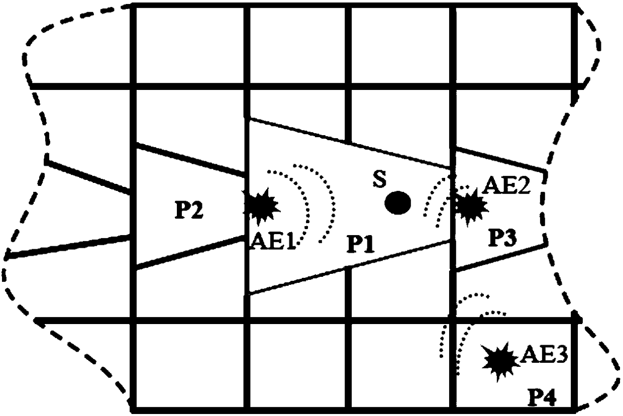
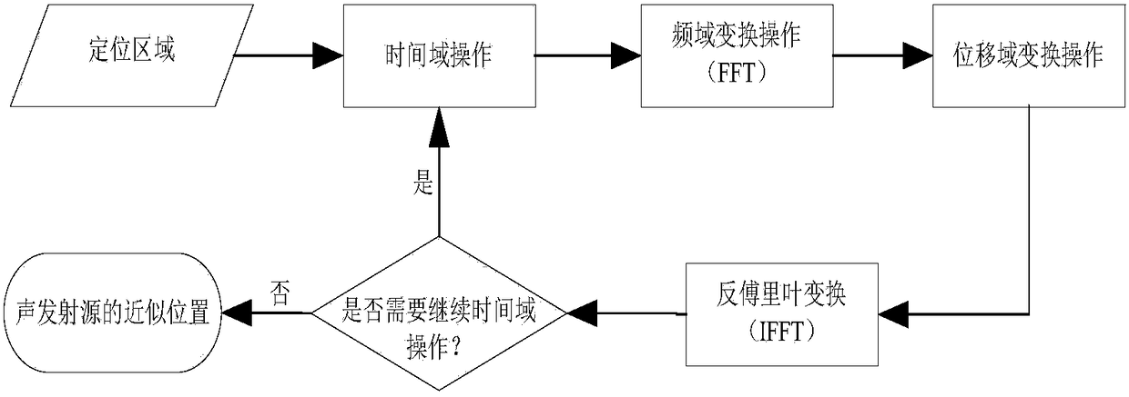
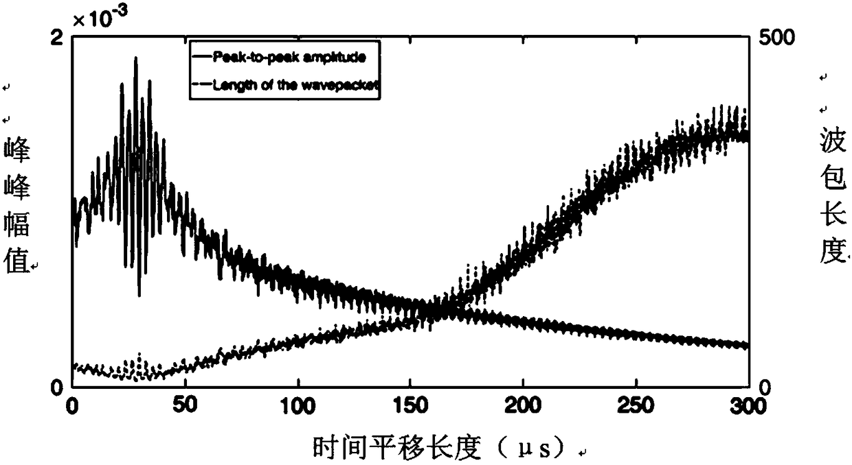
[0017] figure 1 Shown is a schematic diagram of positioning area division, figure 2 Shown is a flow chart of the damage location method for the thermal protection structure of a near-space vehicle, image 3 Shown is a schematic diagram of the peak-to-peak amplitude and the length of the wave packet changing with time, Figure 4 Shown is the acoustic emission signal and the signal map mapped to the displacement space, such as Figure 1 to Figure 4 As shown, in the C / SiC composite thermal protection structure arranged in blocks near the surface of the spacecraft, if the damage location is close to the connection interface between adjacent plates, due to the existence of positioning errors, the damage may be mislocat...


PUM


Abstract

The invention discloses a sound emitting source positioning method, which comprises the following steps of picking lead fracture damage sound emission signals by a sound emission sensor; selecting direct reaching waves in the sound emission signals; performing time domain operation on the direct reaching waves in the sound emission signals; performing frequency domain operation on the direct reaching waves after the execution of the time domain operation; performing displacement domain conversion operation on the direct reaching wave subjected to the execution of frequency domain operation; mapping the signals from the frequency domain to the wave number domain of the signal; mapping the signals of the direct reaching waves subjected to the execution of displacement domain conversion operation to the displacement space; extracting a peak-peak amplitude value and a wave pack length of the signals mapped to the displacement space so as to obtain the change rule of the peak-peak amplitudevalue and the wave pack length along with the phase drift; according to the change rule, judging whether the length of the wave pack is minimum or not when the peak-peak amplitude value reaches the maximum value; determining the position of the sound emission source according to the condition that the transverse moving value on the final time axis dimension is the length of the sound emission source to the sound emission sensor.

Description

technical field [0001] The invention belongs to the technical field of damage monitoring of a thermal protection structure of a near-space vehicle, and in particular relates to a damage location method for a thermal protection structure of a near-space vehicle. Background technique [0002] The near-space vehicle is a new type of aircraft that is closely integrated with aviation and aerospace technologies. It is the main research object in the field of aerospace integration in the world today. It has the capabilities of rapid response, strong penetration, strong destruction, high maneuverability and precise strike. It has been regarded as the strategic commanding heights for safeguarding national security and development interests by developed countries such as the United States, Britain, and France. Near-space vehicles are subject to severe aerodynamic thermal loads during high-speed flight or reentry. In order to ensure that the components inside the vehicle can work norma...

Claims


Application Information

Patent Timeline
IPC IPC(8): G01N29/14G01N29/46
CPCG01N29/14G01N29/46G01N2291/023G01N2291/0289
Inventor 肖登红高勇周小红仝宗凯
Owner BEIJING RES INST OF MECHANICAL & ELECTRICAL TECH
Why Eureka
Try Eureka