Spit electric pressure cooker

An electric pressure cooker and split-type technology, which is used in pressure cookers, cooking utensils, household appliances, etc., can solve problems such as the inability of the lid part and the pot body to transmit current and electrical signals, and hand steam burns.

Pending Publication Date: 2018-06-12
FOSHAN SHUNDE MIDEA ELECTRICAL HEATING APPLIANCES MFG CO LTD
View PDF14 Cites 65 Cited by
  • Summary
  • Abstract
  • Description
  • Claims
  • Application Information

AI Technical Summary

Problems solved by technology

[0002] In the existing split type electric pressure cooker, since the lid part and the body part of the pot can be completely separated, the two parts cannot be connected by wires, resulting in the inability to transmit current and electrical signals between the lid part and the body part. Therefore, the existing products are all It is to set a manual mechanical exhaust valve on the pot cover to realize the exhaust function. When the user needs to control the exhaust valve to exhaust, he can only directly toggle the exhaust valve to exhaust, or press the exhaust button designed on the part of the pot cover. Exhaust, because the operating position is close to the exhaust valve, the user's hand is easily burned by the steam when performing the exhaust operation

Method used


Image

  • Spit electric pressure cooker
  • Spit electric pressure cooker
  • Spit electric pressure cooker

Examples


Embodiment 1

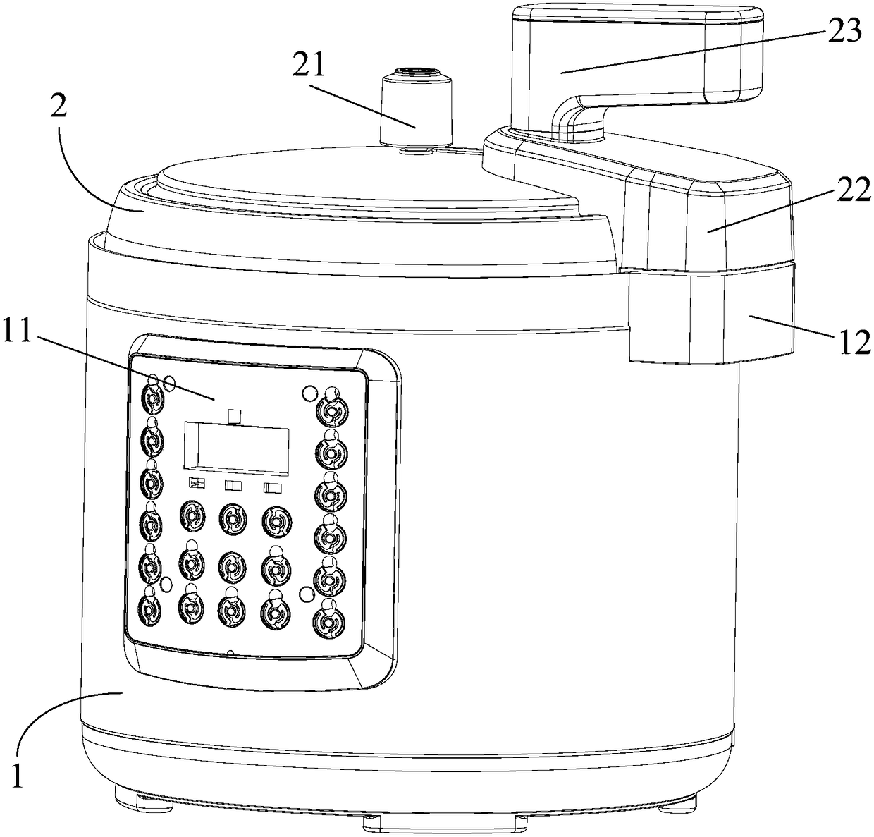
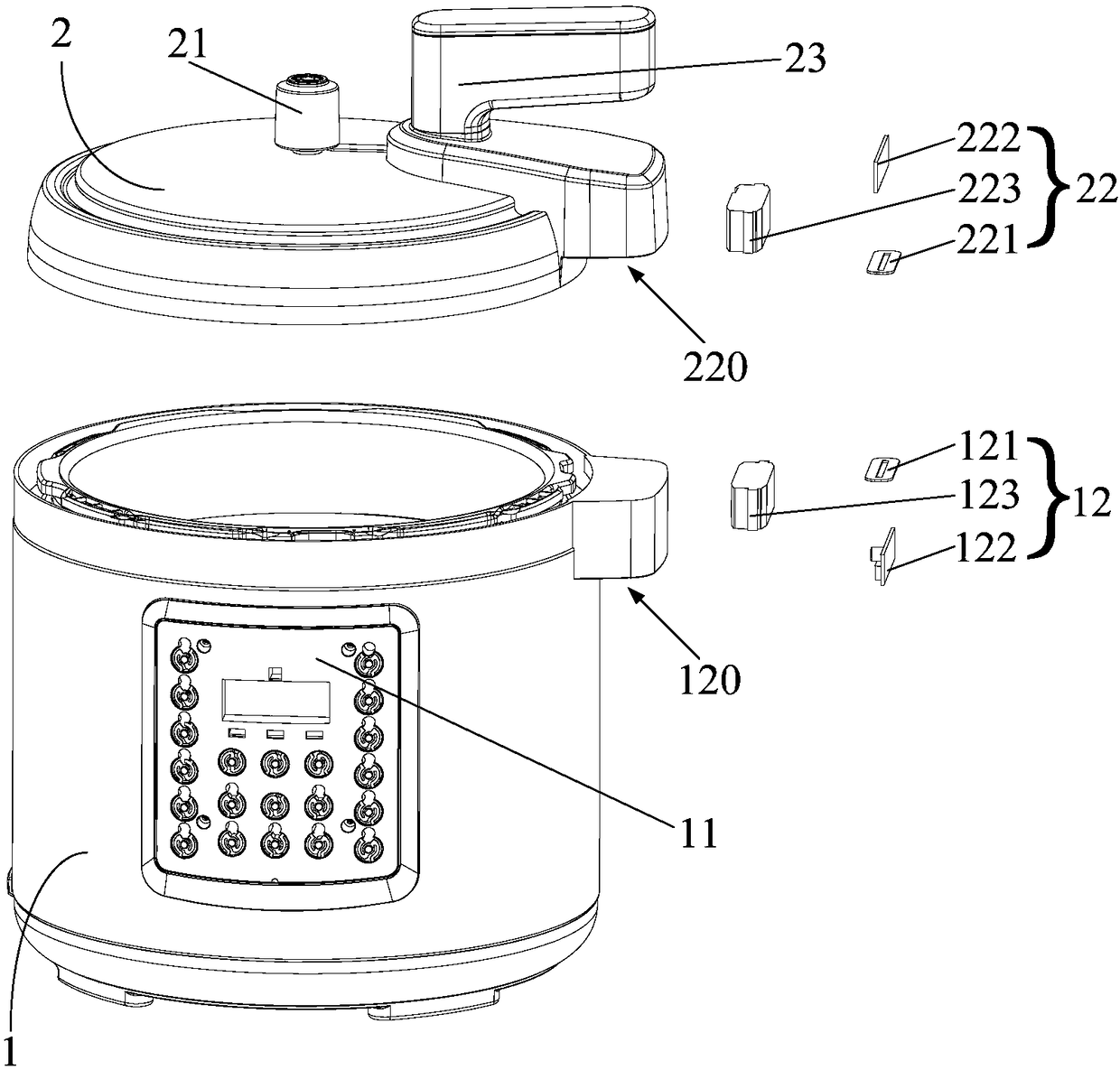
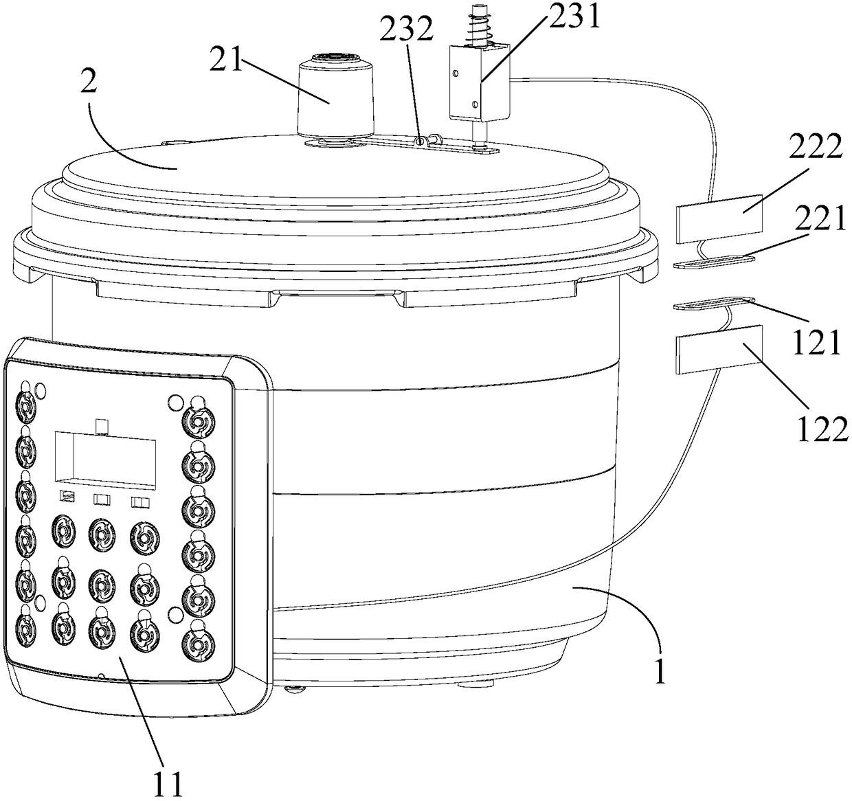
[0048] Such as Figure 1 to Figure 7 As shown, the split type electric pressure cooker includes: a pot body 1, a pot cover 2, a mechanical exhaust valve 21, an electromagnetic drive device 23, an electric energy transmission device 12 and an electric energy receiving device 22, and a control panel 11 is installed on the front of the pot body 1, The control panel 11 is equipped with a main control board (ie a controller), the control panel 11 is provided with an exhaust switch, and the main control board is electrically connected with the exhaust switch and the power supply of the split type electric pressure cooker. The mechanical exhaust valve 21 includes a valve seat 211 and a valve cover 212 , the valve seat 211 is fixedly mounted on the pot cover 2 , and the valve cover 212 is movably mounted on the valve seat 211 . Electromagnetic drive device 23 comprises push-pull type electromagnet 231 and transmission lever 232, and the middle part of transmission lever 232 is connect...

Embodiment 2

[0053]Split type electric pressure cooker includes: pot body, pot cover, mechanical exhaust valve, electromagnetic drive device, electric energy transmission device and electric energy receiving device. device), the control panel is provided with an exhaust switch, and the main control panel is electrically connected with the exhaust switch and the power supply device of the split electric pressure cooker. The mechanical exhaust valve includes a valve seat and a valve cover, the valve seat is fixedly installed on the pot cover, and the valve cover can be movably installed on the valve seat. The electromagnetic driving device includes a push-pull electromagnet and a transmission lever. The middle part of the transmission lever is rotatably connected with the pot cover. The iron core of the push-pull electromagnet can conflict with the upper surface of the first end of the transmission lever, and can push the transmission lever to rotate. The second end of the bonnet engages the...

Embodiment 3

[0057] Split type electric pressure cooker includes: pot body, pot cover, mechanical exhaust valve, electromagnetic drive device, electric energy transmission device and electric energy receiving device. device), the control panel is provided with an exhaust switch, and the main control panel is electrically connected with the exhaust switch and the power supply device of the split electric pressure cooker. The mechanical exhaust valve includes a valve seat and a valve cover, the valve seat is fixedly installed on the pot cover, and the valve cover can be movably installed on the valve seat. The electromagnetic driving device includes a push-pull electromagnet and a transmission lever. The middle part of the transmission lever is rotatably connected with the pot cover. The iron core of the push-pull electromagnet can conflict with the upper surface of the first end of the transmission lever, and can push the transmission lever to rotate. The second end of the bonnet engages th...


PUM


Abstract

The invention provides a spit electric pressure cooker, which comprises a cooker body and a cooker cover, wherein a power supply device is arranged on the cooker body. The spit electric pressure cooker also comprises a mechanical exhaust valve, an electric energy transmission device, an electric energy receiving device and an electromagnetic driving device, wherein the mechanical exhaust valve comprises a valve seat and a valve cover; the valve seat is fixedly arranged on the cooker cover; the valve cover is movably arranged on the valve seat; the electric energy transmission device is arranged on the cooker body and can be electrically connected with the power supply device; the electric energy receiving device is arranged on the cooker cover; the electromagnetic driving device is arranged on the cooker cover and can be electrically connected with the electric energy receiving device; and the electromagnetic driving device is used for driving the valve cover to move so as to open or close the mechanical exhaust valve. According to the scheme, the electric energy transmission device is matched with the electric energy receiving device, so that the electric energy can be realized between the cooker body and the cooker cover, so that the existing manual mechanical type exhaust mode is changed into an electric control type exhaust mode; by using such a design, during the exhausting, a user does not need to manually open the exhaust valve in a near distance, so that the occurrence of the problem of scald injury of the user by steam can be prevented; and the safety of a productis improved.

Description

technical field [0001] The invention relates to the field of cooking utensils, and more specifically, to a split electric pressure cooker. Background technique [0002] In the existing split type electric pressure cooker, since the lid part and the body part of the pot can be completely separated, the two parts cannot be connected by wires, resulting in the inability to transmit current and electrical signals between the lid part and the body part. Therefore, the existing products are all It is to set a manual mechanical exhaust valve on the pot cover to realize the exhaust function. When the user needs to control the exhaust valve to exhaust, he can only directly toggle the exhaust valve to exhaust, or press the exhaust button designed on the part of the pot cover. Exhaust, because the operating position is close to the exhaust valve, the user's hand is easily burned by the steam when performing the exhaust operation. Contents of the invention [0003] The present invent...

Claims


Application Information

Patent Timeline
Patent Type & Authority Applications(China)
IPC IPC(8): A47J27/08A47J36/38A47J27/09
CPCA47J27/08A47J27/0802A47J27/09A47J36/38
Inventor 彭锋
Owner FOSHAN SHUNDE MIDEA ELECTRICAL HEATING APPLIANCES MFG CO LTD
Why Eureka
Try Eureka