Electrostatic chuck

A technology of electrostatic chuck and electrode layer, which is applied in the direction of holding devices, circuits, discharge tubes, etc. that apply electrostatic attraction, and can solve the problems that the in-plane uniformity of plasma density cannot be fully obtained.

Pending Publication Date: 2020-02-11
TOTO LTD
View PDF4 Cites 0 Cited by
  • Summary
  • Abstract
  • Description
  • Claims
  • Application Information

AI Technical Summary

Problems solved by technology

However, there is a problem that the in-plane uniformity of the plasma density may not

Method used


Image

  • Electrostatic chuck
  • Electrostatic chuck
  • Electrostatic chuck

Examples


Embodiment Construction

[0079] Hereinafter, embodiments of the present invention will be described with reference to the drawings. In addition, in each drawing, the same reference numerals are assigned to the same components, and detailed description thereof will be appropriately omitted.

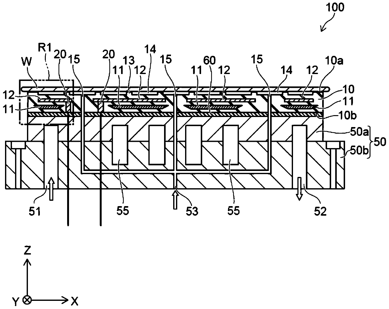
[0080] figure 1 It is a schematic cross-sectional view illustrating an electrostatic chuck according to an embodiment.

[0081] Such as figure 1 As shown, the electrostatic chuck 100 includes a ceramic dielectric substrate 10 , a first electrode layer 11 , a second electrode layer 12 , and a base plate 50 .

[0082] The ceramic dielectric substrate 10 is, for example, a plate-shaped base material formed of sintered ceramics. For example, the ceramic dielectric substrate 10 contains alumina (Al 2 o 3 ). For example, the ceramic dielectric substrate 10 is formed of high-purity alumina. The concentration of alumina in the ceramic dielectric substrate 10 is, for example, 90 mass % or more and 100 mass % or less...


PUM


Abstract

The invention provides an electrostatic chuck capable of increasing the RF responsiveness while increasing the in-plane uniformity of the plasma density. The electrostatic chuck includes a first electrode layer provided inside a ceramic dielectric substrate and connected to a high frequency power supply; a second electrode layer provided inside the ceramic dielectric substrate and connected to a chucking power supply, the first electrode layer being provided between a first major surface and a second major surface in a Z-axis direction, the second electrode layer being provided between the first electrode layer and the first major surface in the Z-axis direction, the first electrode layer having a first surface and a second surface and being supplied with power from the second surface side, the first surface being on the first major surface side, the second surface being on a side opposite to the first surface, a distance along the Z-axis direction between the first surface and the first major surface being constant, a distance along the Z-axis direction between the second surface and the first surface at an end portion of the first electrode layer being shorter than a distance along the Z-axis direction between the second surface and the first surface at a central portion of the first electrode layer.

Description

technical field [0001] Aspects of the present invention generally relate to an electrostatic chuck. Background technique [0002] Electrostatic chucks are used as a means of holding semiconductor wafers, glass substrates, and other processing objects in plasma processing combustion chambers that perform etching, chemical vapor deposition (CVD (Chemical Vapor Deposition)), sputtering, ion implantation, ashing, etc. . The electrostatic chuck is as follows. The electric power for electrostatic adsorption is applied to the built-in electrodes, and substrates such as silicon wafers are adsorbed by electrostatic force. [0003] When plasma processing is performed, for example, a voltage is applied from an RF (Radio Frequency) power supply (high-frequency power supply) to the upper electrode placed above the combustion chamber and the lower electrode placed below the upper electrode to generate plasma. . [0004] In a conventional electrostatic chuck, plasma is generated by usin...

Claims


Application Information

Patent Timeline
IPC IPC(8): H01J37/32H01L21/683
CPCH01J37/32715H01J37/32541H01J37/32568H01L21/6833H02N13/00B23Q3/15
Inventor 籾山大佐佐木均
Owner TOTO LTD
Why Eureka
Try Eureka