Damping device and device with same

The technology of a damping device and a blocking part is applied in the field of damping devices, which can solve the problems of limited deformation space, large assembly workload and high processing cost, and achieve the effects of direct force transmission, large deformation space and simplified structure.

Active Publication Date: 2018-06-12
GREE ELECTRIC APPLIANCES INC
View PDF4 Cites 2 Cited by
  • Summary
  • Abstract
  • Description
  • Claims
  • Application Information

AI Technical Summary

Problems solved by technology

[0004] The disadvantages of this structure include: 1. It is necessary to set the driving structure 160 to transmit the thrust of the torsion spring 180 to the damping device 200, the driving structure 160 and the action member 201 need to be processed into a meshing gear structure, and an independent second rotating shaft 203 needs to be added. The number of required parts is large, resulting in high processing costs, large assembly workload, and large space occupation; and the reaction force of the damping device 200 cannot directly act on the first rotating shaft 140, resulting in the damping device 200 not being able to quickly realize the first rotating shaft 140. Damping effect, the reaction force of the damping device 200 will be lost in the intermediate transmission link, which will affect the damping effect; 2. The ribs on the outer wall of the stationary part 202 and the ribs on the inner wall of the moving part 201 are squeezed to produce a reaction, and the deformation space is limited ; When rubber and other materials are used to prepare ribs, the reaction force that can be generated is relatively small, and the damping effect is poor

Method used


Image

  • Damping device and device with same
  • Damping device and device with same
  • Damping device and device with same

Examples


Embodiment Construction

[0031] The technical solutions of the present invention will be further described below in conjunction with the accompanying drawings and through specific implementation methods.

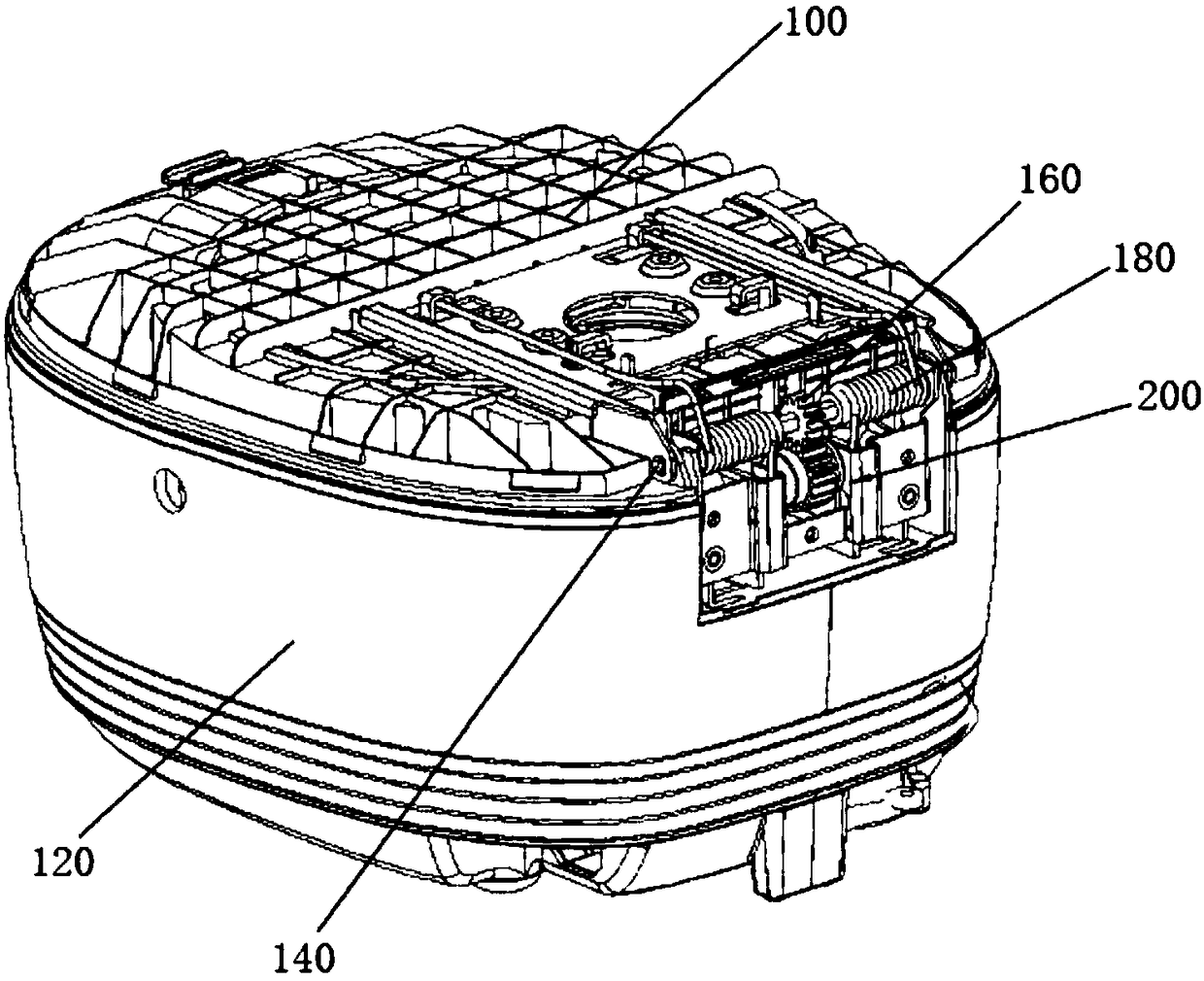
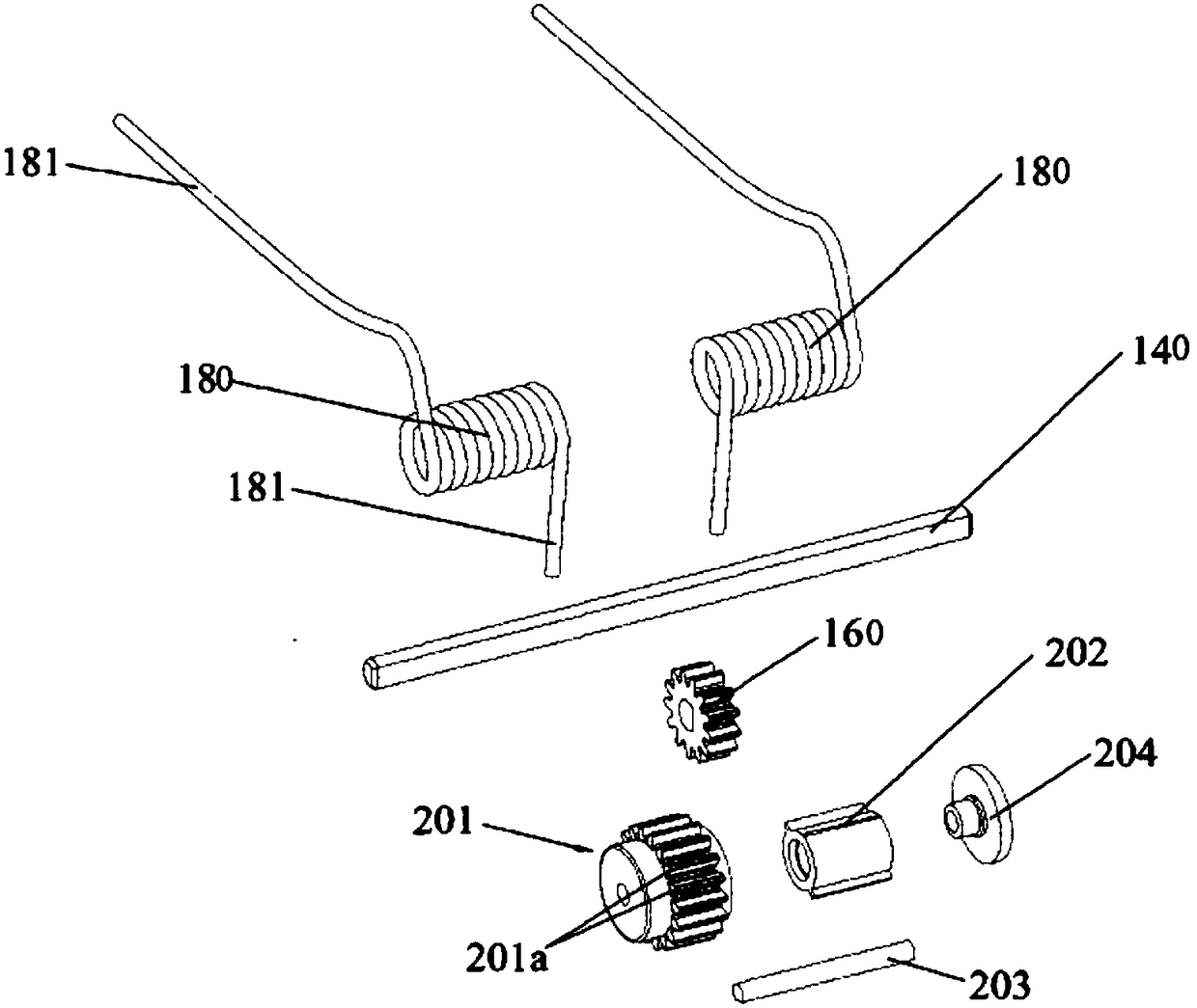
[0032] The invention provides a damping device and a device including the damping device, such as a cooking appliance, more specifically an electric rice cooker. The device includes a first body and a second body connected by a hinge shaft, the outer shell is fixed on the first body or the second body, and the damping device is installed on the hinge shaft. When the device is an electric rice cooker, it includes an upper cover, a pot body, a hinge shaft and a damping device, wherein the semicircular or polygonal hinge shaft is arranged between the upper cover and the pot body, and the damping device is installed on the hinge shaft and fixed on the pot body superior. When the upper cover is opened, the hinge shaft is driven to rotate around the axis. After the hinge shaft rotates to a set position, ...


PUM


Abstract

The invention discloses a damping device and a device with the same, and belongs to the technical field of kitchen appliances and components of the kitchen appliances. By the aid of the damping deviceand the device, the problems of complicated structures, low resistance and the like of existing damping devices can be solved. The damping device comprises a mounting fixing shell cover, a seal cover, clips and an inner core. The shell cover and the seal cover can be closed up to form a closed space, the clips are arranged in the shell cover, and rotating force can be transmitted by hinge shaftsand the inner core; the clips comprise elastic force portions and blocking portions, inner core lugs are arranged on the outer wall of the inner core and are butted onto the blocking portions when theinner core rotates to reach set locations, and elastic force can be provided by the elastic force portions to the blocking portions, so that the rotational speeds of the inner core can be reduced. The damping device and the device with the damping device have the advantages that integral structures can be simplified, only few components are required, accordingly, the cost can be lowered, and thevolume of the device can be diminished; resistance can be provided by the clips, and accordingly the damping device and the device have large deformation spaces and the high elastic force.

Description

technical field [0001] The invention relates to the technical field of kitchen appliances and components thereof, in particular to a damping device and a device comprising the damping device. Background technique [0002] Containers such as rice cookers that require frequent opening of the upper cover usually use a structure such as a torsion spring to drive the upper cover to open. In view of the fact that the driving structure will still exert a relatively large thrust when the upper cover is opened and is about to be put in place, resulting in a violent impact on the connection between the upper cover and the pot body, it is usually necessary to install a damping device. When the upper cover is about to be opened, the damping device provides more and more resistance, slowing down the movement speed of the upper cover until it stops. [0003] The structure and installation position of the existing damping device are as follows: figure 1 and figure 2 As shown, a first r...

Claims


Application Information

Patent Timeline
Patent Type & Authority Applications(China)
IPC IPC(8): A47J36/10A47J36/06
CPCA47J36/06A47J36/10
Inventor 左双全陈群林康桂肖彪孙志辰
Owner GREE ELECTRIC APPLIANCES INC
Why Eureka
Try Eureka